MCP1630DM-DDBS2 Microchip Technology, MCP1630DM-DDBS2 Datasheet - Page 23
MCP1630DM-DDBS2
Manufacturer Part Number
MCP1630DM-DDBS2
Description
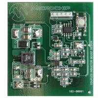
BOARD DEMO BOOST COUPLED INDUCTR
Manufacturer
Microchip Technology
Type
DC/DC Switching Converters, Regulators & Controllersr
Specifications of MCP1630DM-DDBS2
Main Purpose
DC/DC, Step Up
Outputs And Type
1, Non-Isolated
Voltage - Output
15 ~ 40V
Current - Output
30mA
Voltage - Input
3 ~ 5.5V
Regulator Topology
Boost
Frequency - Switching
100kHz
Board Type
Fully Populated
Utilized Ic / Part
MCP1630
Output Voltage
15 V to 40 V
Product
Power Management Modules
For Use With/related Products
MCP1630, PIC12F683
Lead Free Status / RoHS Status
Not applicable / Not applicable
Power - Output
-
Lead Free Status / Rohs Status
Lead free / RoHS Compliant


C.1
© 2006 Microchip Technology Inc.
DEVICE FIRMWARE
For the latest version of the MCP1630 Coupled Inductor Boost Converter Demo Board
firmware, visit the Microchip web site at www.microchip.com.
Appendix C. Demo Board Firmware
CONVERTER DEMO BOARD USER’S GUIDE
Configure GPIO<3> as Input and Enable Port change Interrupt for this Pin
MCP1630 COUPLED INDUCTOR BOOST
Initialise TMR0 for 10 ms and Enable TMR0 Overflow Interrupts
Configure GPIO<2,5> as Output Ports
A
Check for GPIO<3> Pressed
Start the PWM Pulses at
Wake up from SLEEP
Start the V
Check for Key Press
Go to SLEEP Mode
100 kHz Frequency
Initialise Registers
Configure PWM
for > 2 seconds
on key press
Start
B
REF
Yes
Yes
Signal
No
No
DS51612A-page 19
Related parts for MCP1630DM-DDBS2
Image
Part Number
Description
Manufacturer
Datasheet
Request
R

Part Number:
Description:
BOARD DEMO BOOST AUTO INPUT
Manufacturer:
Microchip Technology
Datasheet:

Part Number:
Description:
BOARD CONV DEMO MCP1630 TRPL-OUT
Manufacturer:
Microchip Technology
Datasheet:

Part Number:
Description:
BOARD DEMO FOR MCP1630
Manufacturer:
Microchip Technology
Datasheet:

Part Number:
Description:
BOARD DEMO MCP1630 BIAS SUPPLY
Manufacturer:
Microchip Technology
Datasheet:

Part Number:
Description:
BOARD DEM MCP1630 BOOST MODE LED
Manufacturer:
Microchip Technology
Datasheet:

Part Number:
Description:
Manufacturer:
Microchip Technology Inc.
Datasheet:
Part Number:
Description:
Manufacturer:
Microchip Technology Inc.
Datasheet:
Part Number:
Description:
Manufacturer:
Microchip Technology Inc.
Datasheet:
Part Number:
Description:
Manufacturer:
Microchip Technology Inc.
Datasheet:
Part Number:
Description:
Manufacturer:
Microchip Technology Inc.
Datasheet:
Part Number:
Description:
Manufacturer:
Microchip Technology Inc.
Datasheet: