MCP1630DM-DDBS2 Microchip Technology, MCP1630DM-DDBS2 Datasheet - Page 11
MCP1630DM-DDBS2
Manufacturer Part Number
MCP1630DM-DDBS2
Description
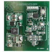
BOARD DEMO BOOST COUPLED INDUCTR
Manufacturer
Microchip Technology
Type
DC/DC Switching Converters, Regulators & Controllersr
Specifications of MCP1630DM-DDBS2
Main Purpose
DC/DC, Step Up
Outputs And Type
1, Non-Isolated
Voltage - Output
15 ~ 40V
Current - Output
30mA
Voltage - Input
3 ~ 5.5V
Regulator Topology
Boost
Frequency - Switching
100kHz
Board Type
Fully Populated
Utilized Ic / Part
MCP1630
Output Voltage
15 V to 40 V
Product
Power Management Modules
For Use With/related Products
MCP1630, PIC12F683
Lead Free Status / RoHS Status
Not applicable / Not applicable
Power - Output
-
Lead Free Status / Rohs Status
Lead free / RoHS Compliant


2.1
2.2
©
2006 Microchip Technology Inc.
INTRODUCTION
FEATURES
Chapter 2. Installation and Operation
The MCP1630 Coupled Inductor Boost Converter Demo Board demonstrates
Microchip's High-Speed Pulse Width Modulator (PWM) used in a coupled inductor
design. When used in conjunction with a microcontroller, the MCP1630 device will
control the power system duty cycle to provide different regulated output voltages using
push button S1. The PIC12F683 microcontroller is used to generate oscillator pulses,
reference voltage and output voltage selection using push button S1. The PIC12F683
can also be programmed to monitor the board ambient temperature using the
MCP9700 Linear Active Thermistor™ device and provide different regulated output
voltages for different thermal readings. The MCP1630 device generates duty cycle
based on various external inputs. External signals include the input oscillator pulses,
reference voltage from PIC12F683 device, and the feedback voltage. The output signal
is a square-wave pulse given to drive the MOSFET.
The PIC12F683 microcontroller is programmable, allowing the user to modify or
develop their own firmware routines to further evaluate the MCP1630 device in this
application.
The MCP1630 Coupled Inductor Boost Converter Demo Board has the following
features.
• With reduced stress on the MOSFET switch, provides greater degree of freedom
• Provides a varied output voltage selection from 15V to 40V in steps of 5V
• Push button select option for the required output voltage selection and ON/OFF
• Tight line and load regulation and high efficiency over entire operating input
• PIC12F683 microcontroller is used to generate the Oscillator pulse and reference
• MCP9700 Linear Active Thermistor device for monitoring the temperature and
• Proprietary features can be added by modifying the firmware contained in the
• The factory programmed source code is available
in selecting the MOSFET
control
voltage range
voltage at required duty cycle
output voltage control
PIC12F683 microcontroller
CONVERTER DEMO BOARD USER’S GUIDE
MCP1630 COUPLED INDUCTOR BOOST
DS51612A-page 7
Related parts for MCP1630DM-DDBS2
Image
Part Number
Description
Manufacturer
Datasheet
Request
R

Part Number:
Description:
BOARD DEMO BOOST AUTO INPUT
Manufacturer:
Microchip Technology
Datasheet:

Part Number:
Description:
BOARD CONV DEMO MCP1630 TRPL-OUT
Manufacturer:
Microchip Technology
Datasheet:

Part Number:
Description:
BOARD DEMO FOR MCP1630
Manufacturer:
Microchip Technology
Datasheet:

Part Number:
Description:
BOARD DEMO MCP1630 BIAS SUPPLY
Manufacturer:
Microchip Technology
Datasheet:

Part Number:
Description:
BOARD DEM MCP1630 BOOST MODE LED
Manufacturer:
Microchip Technology
Datasheet:

Part Number:
Description:
Manufacturer:
Microchip Technology Inc.
Datasheet:
Part Number:
Description:
Manufacturer:
Microchip Technology Inc.
Datasheet:
Part Number:
Description:
Manufacturer:
Microchip Technology Inc.
Datasheet:
Part Number:
Description:
Manufacturer:
Microchip Technology Inc.
Datasheet:
Part Number:
Description:
Manufacturer:
Microchip Technology Inc.
Datasheet:
Part Number:
Description:
Manufacturer:
Microchip Technology Inc.
Datasheet: