STEVAL-CCA012V1 STMicroelectronics, STEVAL-CCA012V1 Datasheet - Page 25
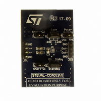
STEVAL-CCA012V1
Manufacturer Part Number
STEVAL-CCA012V1
Description
BOARD EVAL BASED ON TS2007
Manufacturer
STMicroelectronics
Specifications of STEVAL-CCA012V1
Amplifier Type
Class D
Output Type
1-Channel (Mono)
Max Output Power X Channels @ Load
2.8W x 1 @ 4 Ohm
Voltage - Supply
2.4 V ~ 5.5 V
Operating Temperature
-40°C ~ 85°C
Board Type
Fully Populated
Utilized Ic / Part
TS2007
Description/function
Audio Amplifiers
Operating Supply Voltage
2.4 V to 5.5 V
Output Power
3 W
Product
Audio Modules
Silicon Manufacturer
ST Micro
Silicon Core Number
TS2007
Kit Application Type
Amplifier
Application Sub Type
Audio Power Amplifier
Kit Contents
Board
Lead Free Status / RoHS Status
Lead free / RoHS Compliant
For Use With/related Products
TS2007
Other names
497-9004


TS2007
4.10
Output filter considerations
The TS2007 is designed to operate without an output filter. However, due to very sharp
transients on the TS2007 output, EMI radiated emissions may cause some standard
compliance issues.
These EMI standard compliance issues can appear if the distance between the TS2007
outputs and loudspeaker terminal are long (typically more than 50mm, or 100mm in both
directions, to the speaker terminals). As the PCB layout and internal equipment device are
different for each configuration, it is difficult to provide a one-size-fits-all solution.
However, to decrease the probability of EMI issues, there are several simple rules to follow:
●
●
●
●
Figure 51. Ferrite chip bead placement
In the case where the distance between the TS2007 output and the speaker terminals is too
long, it is possible to have low frequency EMI issues due to the fact that the typical operating
frequency is 280kHz. In this configuration, it is necessary to use the output filter represented
in
Figure 1 on page 4
Reduce, as much as possible, the distance between the TS2007 output pins and the
speaker terminals.
Use a ground plane for “shielding” sensitive wires.
Place, as close as possible to the TS2007 and in series with each output, a ferrite bead
with a rated current of minimum 2.5A and impedance greater than 50Ω at frequencies
above 30MHz. If, after testing, these ferrite beads are not necessary, replace them by a
short-circuit.
Allow extra footprint to place, if necessary, a capacitor to short perturbations to ground
(see
Figure
From TS2007 output
51).
as close as possible to the TS2007.
Ferrite chip bead
about 100pF
gnd
Application information
to speaker
25/29
Related parts for STEVAL-CCA012V1
Image
Part Number
Description
Manufacturer
Datasheet
Request
R

Part Number:
Description:
EVAL BOARD CC DRVR HI DENSE LEDS
Manufacturer:
STMicroelectronics
Datasheet:

Part Number:
Description:
EVAL BOARD CC DRVR HI DENSE LEDS
Manufacturer:
STMicroelectronics
Datasheet:

Part Number:
Description:
BATTERY CHARGER CELL PHONE
Manufacturer:
STMicroelectronics
Datasheet:

Part Number:
Description:
BOARD EVAL FOR MEMS SENSORS
Manufacturer:
STMicroelectronics
Datasheet:

Part Number:
Description:
KIT DEV STARTER ST10F276Z5
Manufacturer:
STMicroelectronics
Datasheet:

Part Number:
Description:
BOARD EVAL UPS 450W VOUT=220V
Manufacturer:
STMicroelectronics
Datasheet:

Part Number:
Description:
BOARD STLM75/STDS75/ST72F651
Manufacturer:
STMicroelectronics
Datasheet:

Part Number:
Description:
EVAL BOARD ENERGY METER MONO
Manufacturer:
STMicroelectronics
Datasheet:

Part Number:
Description:
EVAL BOARD ENERGY METER MONO
Manufacturer:
STMicroelectronics
Datasheet:

Part Number:
Description:
EVAL BOARD ENERGY METER MONO
Manufacturer:
STMicroelectronics
Datasheet:

Part Number:
Description:
STMicroelectronics [RIPPLE-CARRY BINARY COUNTER/DIVIDERS]
Manufacturer:
STMicroelectronics
Datasheet:
Part Number:
Description:
STMicroelectronics [LIQUID-CRYSTAL DISPLAY DRIVERS]
Manufacturer:
STMicroelectronics
Datasheet:
Part Number:
Description:
BOARD EVAL FOR MEMS SENSORS
Manufacturer:
STMicroelectronics
Datasheet: