CRD35L01 Cirrus Logic Inc, CRD35L01 Datasheet - Page 4
CRD35L01
Manufacturer Part Number
CRD35L01
Description
REF DESIGN W/BRD FOR CS35L0X
Manufacturer
Cirrus Logic Inc
Datasheet
1.CRD35L01.pdf
(14 pages)
Specifications of CRD35L01
Amplifier Type
Class D
Output Type
1-Channel (Mono)
Max Output Power X Channels @ Load
1.7W x 1 @ 8 Ohm
Voltage - Supply
2.5 V ~ 5.5 V
Board Type
Fully Populated
Utilized Ic / Part
CS35L0X
Description/function
Audio Amplifiers
Operating Supply Voltage
2.5 V to 5.5 V
Output Power
1.4 W, 1.7 W
Product
Audio Modules
For Use With/related Products
CS35L01
Lead Free Status / RoHS Status
Contains lead / RoHS non-compliant
Operating Temperature
-
Lead Free Status / Rohs Status
Lead free / RoHS Compliant
Other names
598-1804


4
1. SYSTEM OVERVIEW
The CRD35L01 reference design is a practical means for evaluating the CS35L01 high-efficiency Class-D audio am-
plifier with idle current consumption. A differential mono analog input signal interface is provided. Optional input gain
and output filtering component placeholders are provided for easy modification to custom tune the CS35L01 for the
user’s specific system requirements.
1.1
1.2
1.3
1.4
1.5
1.5.1
CS35L01 Hybrid Class-D Amplifier
The CS35L01 Hybrid Class-D amplifier is a mono, full-bridge, closed-loop, +6-dB gain, audio amplifier avail-
able in a 9-ball, WLCSP package. A complete description of the CS35L01 device is included in the CS35L01
product data sheet.
Power Supply
A single +2.5 to +5.5 VDC power supply is required to power the CRD35L01. The supply must be capable
of delivering sufficient current for the intended power output. The supply provides power to the CS35L01.
The power supply connection to the board is provided by the header J4. The positive terminal is labeled
VBATT. The ground terminal is labeled GND.
Operational Modes
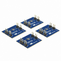
The CS35L01 device has four operational modes, each of which require slightly different hardware connec-
tions. Four boards are available to illustrate the hardware design differences between each of the four
modes. More information on the specifics of each operational mode can be found in the CS35L01/03 prod-
uct datasheet. The CRD names listed below are populated with a CS35L01 device.
•
•
•
•
The CRD35L01-SD schematic is shown in
Figure 3 on page
schematic is shown in
Shutdown Control
The J2 header contains shutdown control for the CS35L01 device. Placing a jumper across the J2 header
pulls the SD line LOW and shuts down the amplifier. When no jumper is present, the SD line is pulled HIGH
by the R3 resistor, enabling normal operation.
Amplifier Gain
The amplifier gain of the CS35L01 device is +6 dB by default. The amplifier gain can be reduced through
the use of the optional input gain adjustment resistors on the CRD35L01.
Optional Input Gain Adjustment Resistors
The CRD35L01 contains optional gain adjustment resistor placeholders (R1 and R2). By default, these
placeholders are not populated and are bypassed with a signal trace configuring the CS35L01 to operate
at its default gain. The gain adjustment resistors are necessary only when a gain of +6 dB is not desired.
CRD35L01-SD: Standard Class-D Mode
CRD35L01-FSD: Reduced-Frequency Standard Class-D Mode
CRD35L01-HD: Hybrid Class-D Mode
CRD35L01-FHD: Reduced-Frequency Hybrid Class-D Mode
8. The CRD35L01-HD schematic is shown in
Figure 5 on page
8.
Figure 2 on page
8. The CRD35L01-FSD schematic is shown in
Figure 5 on page
8. The CRD35L01-FHD
CRD35L01
DS914RD2
Related parts for CRD35L01
Image
Part Number
Description
Manufacturer
Datasheet
Request
R

Part Number:
Description:
Audio Modules & Development Tools EvalBd 30W Qd Hlf- Brdg Dig Amp Pwr Stg
Manufacturer:
Cirrus Logic Inc
Datasheet:
Part Number:
Description:
Audio Modules & Development Tools Eval Bd PWM Contrlr+ PwrStg_2Lyr 1oz Cu
Manufacturer:
Cirrus Logic Inc
Datasheet:

Part Number:
Description:
Audio Modules & Development Tools Ref bd for spkrbar MSA & DSP products
Manufacturer:
Cirrus Logic Inc
Datasheet:

Part Number:
Description:
Audio Modules & Development Tools Ref Bd LP Mlt-Ch Decimation Filter
Manufacturer:
Cirrus Logic Inc
Datasheet:
Part Number:
Description:
Audio Modules & Development Tools Eval Bd PWM Contrlr+ PwrStg_4Lyr 1oz Cu
Manufacturer:
Cirrus Logic Inc
Datasheet:
Part Number:
Description:
Audio Modules & Development Tools Ref Bd Low-volt Stereo CODEC
Manufacturer:
Cirrus Logic Inc
Datasheet:
Part Number:
Description:
Audio Modules & Development Tools Eval Bd 32-Bit HD Audio Decoder DSP
Manufacturer:
Cirrus Logic Inc
Part Number:
Description:
Audio Modules & Development Tools Eval Bd for Dig. Amp Controllers
Manufacturer:
Cirrus Logic Inc
Datasheet:
Part Number:
Description:
Audio Modules & Development Tools Ref Bd LP Sngl-Ch Decimation Filter
Manufacturer:
Cirrus Logic Inc
Datasheet:
Part Number:
Description:
Audio Modules & Development Tools Ref Bd 10Mbps Ethernet Controller
Manufacturer:
Cirrus Logic Inc
Part Number:
Description:
Audio Modules & Development Tools EvalBd 30W Qd Hlf- Brdg Dig Amp Pwr Stg
Manufacturer:
Cirrus Logic Inc
Datasheet:

Part Number:
Description:
EVALUATION BOARD FOR CS8427
Manufacturer:
Cirrus Logic Inc
Datasheet:

Part Number:
Description:
BOARD EVAL FOR CS8416 RCVR
Manufacturer:
Cirrus Logic Inc
Datasheet:

Part Number:
Description:
EVALUATION BOARD FOR CS8420
Manufacturer:
Cirrus Logic Inc
Datasheet:

Part Number:
Description:
KIT DEVELOPMENT EP9315 ARM9
Manufacturer:
Cirrus Logic Inc
Datasheet: