EVAL-AD7767-1EDZ Analog Devices Inc, EVAL-AD7767-1EDZ Datasheet - Page 18
EVAL-AD7767-1EDZ
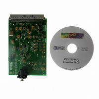
Manufacturer Part Number
EVAL-AD7767-1EDZ
Description
BOARD EVAL AD7767-1 64KSPS 111DB
Manufacturer
Analog Devices Inc
Specifications of EVAL-AD7767-1EDZ
Number Of Adc's
1
Number Of Bits
24
Sampling Rate (per Second)
64k
Data Interface
Serial
Inputs Per Adc
1 Differential
Input Range
±VREF
Power (typ) @ Conditions
10.5mW @ 64kSPS
Voltage Supply Source
Analog and Digital
Operating Temperature
-40°C ~ 105°C
Utilized Ic / Part
AD7767-1
Lead Free Status / RoHS Status
Lead free / RoHS Compliant


AD7767
DAISY CHAINING
Daisy chaining devices allows numerous devices to use the same
digital interface lines by cascading the outputs of multiple ADCs
on a single data line. This feature is especially useful for reduc-
ing component count and wiring connections, for example, in
isolated multiconverter applications or for systems with a limited
interfacing capacity. Data readback is analogous to clocking a
shift register where data is clocked on the falling edge of SCLK.
The block diagram in Figure 36 shows how devices must be
connected to achieve daisy-chain functionality. The scheme
shown operates by passing the output data of the SDO pin of an
AD7767 device to the SDI input of the next AD7767 device in
the chain. The data then continues through the chain until it is
clocked onto the SDO pin of the first device in the chain.
READING DATA IN DAISY-CHAIN MODE
An example of a daisy chain of four AD7767 devices is shown in
Figure 36 and Figure 37. In the case illustrated in Figure 36, the
output of the AD7767 labeled A is the output of the full daisy
chain. The last device in the chain (the AD7767 labeled D) has
its serial data input (SDI) pin connected to ground. All the
devices in the chain must use common MCLK, SCLK, CS , and
SYNC / PD signals.
To enable the daisy-chain conversion process, apply a common
SYNC / PD pulse to all devices, synchronizing all the devices in
the chain (see the
section).
After applying a SYNC / PD pulse to all the devices, there is a
delay (as listed in
at the output of the chain of devices. As shown in
first conversion result is output from the AD7767 device labeled
A. This 24-bit conversion result is followed by the conversion
results from the devices labeled B, C, and D, respectively, with
all conversion results output in an MSB-first sequence. The
stream of conversion results is clocked through each device in
the chain and is eventually clocked onto the SDO pin of the
AD7767 device labeled A. The conversion results of all the
devices in the chain must be clocked onto the SDO pin of the
final device in the chain while its
Table 7
Power-Down, Reset, and Synchronization
) before valid conversion data appears
DRDY signal is active low.
Figure 37
, the
Rev. C | Page 18 of 24
This is illustrated in the examples shown (
where the conversion results from the devices labeled A, B, C,
and D are clocked onto SDO (A) during the time between the
falling edge of
CHOOSING THE SCLK FREQUENCY
As shown in Figure 37, the number of SCLK falling edges that
occur during the period when DRDY (A) is active low must
match the number of devices in the chain multiplied by 24 (the
number of bits that must be clocked through onto SDO (A) for
each device).
The period of SCLK (t
length using a known common MCLK frequency must,
therefore, be established in advance. Note that the maximum
SCLK frequency is governed by t
Specifications table for different V
In the case where CS is tied logic low,
where:
K is the number of AD7767 devices in the chain.
t
t
In the case where CS is used in the daisy-chain interface,
where:
K is the number of AD7767 devices in the chain.
t
t
Note that the maximum value of SCLK is governed by t
specified in the Timing Specifications table for different V
voltages.
SCLK
READ
SCLK
READ
is the period of the SCLK.
is the period of the SCLK.
equals t
equals t
t
t
SCLK
SCLK
≤
≤
DRDY
⎡
⎢
⎣
DRDY
⎡
⎢
⎣
(
24
t
DRDY (A) and the rising edge of DRDY (A).
t
READ
READ
×
− t
− t
K
) (
5
5
.
.
−
⎤
⎥
⎦
24
SCLK
t
6
×
) required for a known daisy-chain
+
K
t
7
+
t
8
13
and is specified in the Timing
DRIVE
)
⎤
⎥
⎦
voltages.
Figure 37
and
Figure 38
8
and is
DRIVE
(1)
(2)
),
Related parts for EVAL-AD7767-1EDZ
Image
Part Number
Description
Manufacturer
Datasheet
Request
R

Part Number:
Description:
IC, ADJ LDO REG, 1.5V TO 5V 250mA MSOP-8
Manufacturer:
Vishay
Datasheet:

Part Number:
Description:
IC, ADJ LDO REG, 1.5V TO 5V 0.6A 8-TSSOP
Manufacturer:
Vishay
Datasheet:
Part Number:
Description:
IC, ADJ LDO REG, 1.5V TO 5V 250mA MSOP-8
Manufacturer:
Vishay
Datasheet:

Part Number:
Description:
IC ADJ LDO REG 1.5V TO 5V 150mA 5-SOT-23
Manufacturer:
Vishay
Datasheet:

Part Number:
Description:
BOARD EVAL AS1324-AD
Manufacturer:
austriamicrosystems
Datasheet:
Part Number:
Description:
IC, ADJ LDO REG, 1.5V TO 5V 0.6A 8-TSSOP
Manufacturer:
Vishay
Datasheet:

Part Number:
Description:
IC, ADJ LDO REG, 1.5V TO 5V, 0.3A, MSOP8
Manufacturer:
Vishay
Datasheet:
Part Number:
Description:
IC, ADJ LDO REG, 1.5V TO 5V, 0.3A, MSOP8
Manufacturer:
Vishay
Datasheet:
Part Number:
Description:
IC, ADJ LDO REG 1.215V TO 5V 0.3A MSOP-8
Manufacturer:
Vishay
Datasheet:
Part Number:
Description:
IC, ADJ LDO REG 1.215V TO 5V 0.3A MSOP-8
Manufacturer:
Vishay
Datasheet:

Part Number:
Description:
±1.7g Dual-Axis IMEMS Accelerometer Evaluation Board
Manufacturer:
Analog Devices Inc
Datasheet:

Part Number:
Description:
IC MULTIPLIER ANALOG 8-SOIC T/R
Manufacturer:
Analog Devices Inc
Datasheet:

Part Number:
Description:
IC ANALOG MULTIPLIER 8-DIP
Manufacturer:
Analog Devices Inc
Datasheet:
Part Number:
Description:
IC ANALOG MULTIPLIER 8-SOIC
Manufacturer:
Analog Devices Inc
Datasheet:
Part Number:
Description:
IC ANALOG MULTIPLIER 8-DIP
Manufacturer:
Analog Devices Inc
Datasheet: