MCP3909EV-MCU16 Microchip Technology, MCP3909EV-MCU16 Datasheet - Page 30
MCP3909EV-MCU16
Manufacturer Part Number
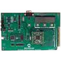
MCP3909EV-MCU16
Description
EVALUATION BOARD FOR MCP3909
Manufacturer
Microchip Technology
Datasheets
1.MCP3909T-ISS.pdf
(44 pages)
2.MCP3909T-ISS.pdf
(104 pages)
3.MCP3909EV-MCU16.pdf
(38 pages)
Specifications of MCP3909EV-MCU16
Number Of Adc's
2
Number Of Bits
16
Sampling Rate (per Second)
15k
Data Interface
Serial
Inputs Per Adc
1 Differential
Input Range
±1 V
Voltage Supply Source
Analog and Digital
Operating Temperature
-40°C ~ 85°C
Utilized Ic / Part
MCP3909
Silicon Manufacturer
Microchip
Application Sub Type
ADC
Kit Application Type
Data Converter
Silicon Core Number
MCP3909
Kit Contents
Board
Lead Free Status / RoHS Status
Lead free / RoHS Compliant


MCP3909
5.7
With microcontroller SPI ports, it is required to send
groups of eight bits. It is also required that the
microcontroller SPI port be configured to clock out data
on the falling edge of clock and latch data in on the
rising edge, or vice versa depending on the mode.
TABLE 5-4:
DS22025B-page 30
Standard SPI
Terminology
Mode
0,0
0,1
1,0
1,1
Using the MCP3909 with
Microcontroller (MCU) SPI Ports
SPI MODE COMPATIBILITY
PIC Control Bits
CKP
0
0
1
1
State
CKE
1
0
1
0
Compatibility
MCP3909
—
—
—
√
Idle state for clock is low level, transmit (from PIC)
occurs from active to idle clock state
Idle state for clock is low level, transmit (from PIC)
occurs from idle to active clock state
Idle state for clock is high level, transmit (from PIC)
occurs from active to idle clock state
Idle state for clock is high level, transmit (from PIC)
occurs from idle to active clock state
5.7.1
The following table represents the standard SPI mode
terminology, the respective PIC bit settings, and a
description of compatibility for the MCP3909 device.
The MCP3909 works in SPI mode 0,1 mode, that is the
data is clocked out of the part on the rising edge and
clocked in on the falling edge of SCK.
SPI MODE DEFINITIONS
Description
© 2009 Microchip Technology Inc.
Related parts for MCP3909EV-MCU16
Image
Part Number
Description
Manufacturer
Datasheet
Request
R

Part Number:
Description:
Manufacturer:
Microchip Technology Inc.
Datasheet:
Part Number:
Description:
Manufacturer:
Microchip Technology Inc.
Datasheet:
Part Number:
Description:
Manufacturer:
Microchip Technology Inc.
Datasheet:
Part Number:
Description:
Manufacturer:
Microchip Technology Inc.
Datasheet:
Part Number:
Description:
Manufacturer:
Microchip Technology Inc.
Datasheet:
Part Number:
Description:
Manufacturer:
Microchip Technology Inc.
Datasheet:
Part Number:
Description:
Manufacturer:
Microchip Technology Inc.
Datasheet:
Part Number:
Description:
Manufacturer:
Microchip Technology Inc.
Datasheet: