DEMOBOARD TLE 7209-2R Infineon Technologies, DEMOBOARD TLE 7209-2R Datasheet - Page 9
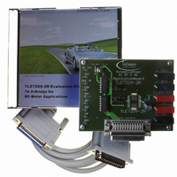
DEMOBOARD TLE 7209-2R
Manufacturer Part Number
DEMOBOARD TLE 7209-2R
Description
BOARD DEMO FOR TLE 7209-2R
Manufacturer
Infineon Technologies
Datasheet
1.TLE7209-2R.pdf
(32 pages)
Specifications of DEMOBOARD TLE 7209-2R
Main Purpose
Power Management, Motor Control
Embedded
No
Utilized Ic / Part
TLE7209-2R
Primary Attributes
1 H-Bridge Driver
Secondary Attributes
Short-Circuit, Thermal & Undervoltage Protection
Lead Free Status / RoHS Status
Lead free / RoHS Compliant
Other names
DEMOBOARDTLE7209-2RIN


2.4.1
2.4.1.1
In SF-mode, pin 2 is used as an open-drain output status-flag. The pin has to be pulled
to the logic supply voltage with a pull-up resistor, 47 kOhm recommended.
In case of any failure that leads to a shut-down of the outputs, the status-flag is set (e.g.
SF pin pulled to low). These failures are:
– Under Voltage on
– Short circuit of OUT1 or OUT2 against
– Short circuit between OUT1 and OUT2
– Over-current
– Over-temperature
SF is also pulled low when the outputs are disabled by EN or DIS.
2.4.1.2
– In case of under-Voltage, the failure is not latched. As soon as
– In the SF-mode, all internal circuitry is supplied by the voltage on
– In case of short circuit, over-current or over-temperature, the fault will be stored.
2.4.2
2.4.2.1
The serial SPI interface establishes a communication link between TLE 7209-2R and the
systems microcontroller. The TLE 7209-2R always operates in slave mode whereas the
controller provides the master function. The maximum baud rate is 2 MBaud (200pF on
SDO).
By applying an active slave select signal at CSN the TLE 7209-2R is selected by the SPI
master. SDI is the data input (Slave In), SDO the data output (Slave Out). Via SCK
(Serial Clock Input) the SPI clock is provided by the master. In case of inactive slave
select signal (High) the data output SDO goes into tristate.
Final Datasheet
under-Voltage detection threshold, the output stage switches in tristate and the status-
flag is set from high level to low-level. If the voltage has risen above the specified value
again, the output stage switches on again and the status-flag is reset to high-level.
The Under Voltage failure is shown at the SF pin for
detection threshold (typical 4.2V) down to 2.5V.
a loss of
Reset). This Power-ON-Reset occurs as soon as under-Voltage is detected on
The output stage remains in tristate and the status-flag at low-level until the error is
reset by one of the following conditions: H -> L on DIS, L -> H on EN or Power-ON
Reset.
Status-Flag (SF) Mode (DMS = GND)
SF output
Fault storage and reset
SPI-Mode (DMS = 5V)
SPI-Interface
V
S
supply voltage leads to a reset of all stored information (Power-ON-
V
S
V
S
9
or GND
V
S
in the voltage range below the
Circuit Description
V
V
S
. For that reason,
S
V1.3, 2005-jan-11
TLE 7209-2R
falls below the
V
S
Related parts for DEMOBOARD TLE 7209-2R
Image
Part Number
Description
Manufacturer
Datasheet
Request
R

Part Number:
Description:
BOARD DEMO FOR T7024PGM
Manufacturer:
Atmel
Datasheet:

Part Number:
Description:
BOARD DEMO FOR U4091BM
Manufacturer:
Atmel
Datasheet:

Part Number:
Description:
BOARD DEMO FOR TLE6208-3G
Manufacturer:
Infineon Technologies
Datasheet:

Part Number:
Description:
BOARD DEMO TLE8201R V1.0
Manufacturer:
Infineon Technologies
Datasheet:

Part Number:
Description:
BOARD DEMO FOR TLE6208-6G
Manufacturer:
Infineon Technologies
Datasheet:

Part Number:
Description:
BOARD DEMO FOR TLE 6288R
Manufacturer:
Infineon Technologies
Datasheet:

Part Number:
Description:
BOARD DEMO FOR TLE 6214L
Manufacturer:
Infineon Technologies
Datasheet:


Part Number:
Description:
BOARD DEMO PROFET V2.0BTS
Manufacturer:
Infineon Technologies
Datasheet:

Part Number:
Description:
Manufacturer:
Infineon Technologies AG
Datasheet:
Part Number:
Description:
Manufacturer:
Infineon Technologies AG
Datasheet:
Part Number:
Description:
Manufacturer:
Infineon Technologies AG
Datasheet:
Part Number:
Description:
Manufacturer:
Infineon Technologies AG
Datasheet:
Part Number:
Description:
Manufacturer:
Infineon Technologies AG
Datasheet: