DEMOBOARD TLE 7209-2R Infineon Technologies, DEMOBOARD TLE 7209-2R Datasheet - Page 10
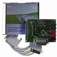
DEMOBOARD TLE 7209-2R
Manufacturer Part Number
DEMOBOARD TLE 7209-2R
Description
BOARD DEMO FOR TLE 7209-2R
Manufacturer
Infineon Technologies
Datasheet
1.TLE7209-2R.pdf
(32 pages)
Specifications of DEMOBOARD TLE 7209-2R
Main Purpose
Power Management, Motor Control
Embedded
No
Utilized Ic / Part
TLE7209-2R
Primary Attributes
1 H-Bridge Driver
Secondary Attributes
Short-Circuit, Thermal & Undervoltage Protection
Lead Free Status / RoHS Status
Lead free / RoHS Compliant
Other names
DEMOBOARDTLE7209-2RIN


The first two bits of an instruction may be used to establish an extended device-
addressing. This gives the opportunity to operate up to 4 Slave-devices sharing one
common CSN signal from the Master-Unit (see Figure 7)
Figure 6
2.4.2.2
1. When DMS is > 3.5V, the SPI is active, independently of the state of EN or DIS. During
2. If the slave select signal at CSN is inactive (high), the state machine is forced to enter
3. During active (low) state of the select signal CSN the falling edge of the serial clock
4. Chip-address:
5. Verification byte:
Final Datasheet
D M S
C S N
S C K
S D I
S D O
D I S
E N
active reset conditions (DMS < 3.5V) the SPI is driven into its default state. When reset
becomes inactive, the state machine enters into a wait-state for the next instruction.
the wait-state, i.e. the state machine waits for the following instruction.
signal SCK will be used to latch the input data at SDI. Output data at SDO are driven
with the rising edge of SCK (see timing diagram Figure 13)
In order to establish the option of extended addressing the uppermost two bits of the
instruction-byte (i.e the first two SDI-bits of a Frame) are reserved to send a chip-
address. To avoid a bus conflict the output SDO must stay high impedance during the
addressing phase of a frame (i.e. until the address-bits are recognized as valid chip-
address). If the chip-address does not match, the data at SDI will be ignored and SDO
remains high impedance for the complete frame. See also Figure 7
Simultaneously to the receipt of an SPI instruction TLE 7209-2R transmits a
verification byte via the output SDO to the controller. Refer to Figure 8. This byte
indicates normal or abnormal operation of the SPI. It contains an initial bit pattern and
a flag indicating an error occurred during the previous access.
Characteristics of the SPI Interface
SPI block-diagram
s h if t - r e g is t e r
O R
8
10
D I A _ R E G
R e s e t
8
S P I - C o n t r o l:
- > s t a t e m a c h in e
- > c lo c k c o u n t e r
- > in s t r u c t io n r e c o g n it io n
D ia g n o s t ic s
S P I p o w e r -
v o lt a g e
U n d e r -
Circuit Description
D M S
s u p p ly
V1.3, 2005-jan-11
TLE 7209-2R
Related parts for DEMOBOARD TLE 7209-2R
Image
Part Number
Description
Manufacturer
Datasheet
Request
R

Part Number:
Description:
BOARD DEMO FOR T7024PGM
Manufacturer:
Atmel
Datasheet:

Part Number:
Description:
BOARD DEMO FOR U4091BM
Manufacturer:
Atmel
Datasheet:

Part Number:
Description:
BOARD DEMO FOR TLE6208-3G
Manufacturer:
Infineon Technologies
Datasheet:

Part Number:
Description:
BOARD DEMO TLE8201R V1.0
Manufacturer:
Infineon Technologies
Datasheet:

Part Number:
Description:
BOARD DEMO FOR TLE6208-6G
Manufacturer:
Infineon Technologies
Datasheet:

Part Number:
Description:
BOARD DEMO FOR TLE 6288R
Manufacturer:
Infineon Technologies
Datasheet:

Part Number:
Description:
BOARD DEMO FOR TLE 6214L
Manufacturer:
Infineon Technologies
Datasheet:


Part Number:
Description:
BOARD DEMO PROFET V2.0BTS
Manufacturer:
Infineon Technologies
Datasheet:

Part Number:
Description:
Manufacturer:
Infineon Technologies AG
Datasheet:
Part Number:
Description:
Manufacturer:
Infineon Technologies AG
Datasheet:
Part Number:
Description:
Manufacturer:
Infineon Technologies AG
Datasheet:
Part Number:
Description:
Manufacturer:
Infineon Technologies AG
Datasheet:
Part Number:
Description:
Manufacturer:
Infineon Technologies AG
Datasheet: