NCP370GEVB ON Semiconductor, NCP370GEVB Datasheet - Page 7
NCP370GEVB
Manufacturer Part Number
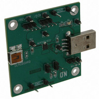
NCP370GEVB
Description
EVAL BOARD FOR NCP370G
Manufacturer
ON Semiconductor
Specifications of NCP370GEVB
Design Resources
NCP370GEVB BOM NCP370GEVB Gerber Files NCP370GEVB Schematic
Main Purpose
Overvoltage Protection
Embedded
No
Utilized Ic / Part
NCP370
Primary Attributes
Overvoltage Protected up to 28V and down to -28V
Secondary Attributes
Reverse Mode
Lead Free Status / RoHS Status
Lead free / RoHS Compliant
For Use With/related Products
NCP370G
Other names
NCP370GEVBOS


DIR Input
DIR pin shall be forced to low and REV to high. A high level
on the DIR pin disconnects OUT pin from IN pin. DIR does
not over−ride an OVLO or UVLO fault (FLAG status is still
available).
Table 1. FLAG TABLE
To enable Direct Charge operation (Direct Mode), the
DIR
0
0
0
0
1
1
1
micro−controller
REV
0
0
1
1
0
1
1
FLAG
REV
V
DIR
out
V
in
UVLO < V
UVLO < V
UVLO < V
1.5 < V
1.5 < V
1.5 < V
= V
ton
V
V
out
V
rev
in
in
in
> OVLO
−DROPOUT
in
in
in
> OVLO
> OVLO
IN
in
< UVLO or
< UVLO or
< UVLO or
in
in
< OVLO
< OVLO
< OVLO
oo
Figure 4. FLAG status in Reverse Mode
oo
External Accessory ID = 1
http://onsemi.com
= V
= V
V
in
in
out
−DROPOUT
−DROPOUT
OUT
7
Hiz
Hiz
Hiz
Hiz
> 2.5 V
Table 2. TABLE SELECTION OF CHARGE MODES
DIR
0
0
1
1
Status
FLAG
High
High
High
High
Low
Low
Low
REV
0
1
0
1
Pass Element (Dual NMOS FET)
micro−controller
Enhance Mode
Reverse Mode
Disable Mode
Direct Mode
Mode
Close
Close
Close
Open
Open
Open
Open
Battery
Output
Related parts for NCP370GEVB
Image
Part Number
Description
Manufacturer
Datasheet
Request
R

Part Number:
Description:
Positive and Negative Overvoltage Protection
Manufacturer:
ON Semiconductor
Datasheet:
Part Number:
Description:
ON Semiconductor [VOLTAGE REGULATOR]
Manufacturer:
ON Semiconductor
Datasheet:
Part Number:
Description:
357-036-542-201 CARDEDGE 36POS DL .156 BLK LOPRO
Manufacturer:
ON Semiconductor
Datasheet:
Part Number:
Description:
357-036-542-201 CARDEDGE 36POS DL .156 BLK LOPRO
Manufacturer:
ON Semiconductor
Datasheet:
Part Number:
Description:
357-036-542-201 CARDEDGE 36POS DL .156 BLK LOPRO
Manufacturer:
ON Semiconductor
Datasheet:
Part Number:
Description:
357-036-542-201 CARDEDGE 36POS DL .156 BLK LOPRO
Manufacturer:
ON Semiconductor
Datasheet:
Part Number:
Description:
357-036-542-201 CARDEDGE 36POS DL .156 BLK LOPRO
Manufacturer:
ON Semiconductor
Datasheet:
Part Number:
Description:
357-036-542-201 CARDEDGE 36POS DL .156 BLK LOPRO
Manufacturer:
ON Semiconductor
Datasheet:
Part Number:
Description:
357-036-542-201 CARDEDGE 36POS DL .156 BLK LOPRO
Manufacturer:
ON Semiconductor
Datasheet:
Part Number:
Description:
357-036-542-201 CARDEDGE 36POS DL .156 BLK LOPRO
Manufacturer:
ON Semiconductor
Datasheet:
Part Number:
Description:
357-036-542-201 CARDEDGE 36POS DL .156 BLK LOPRO
Manufacturer:
ON Semiconductor
Datasheet:
Part Number:
Description:
357-036-542-201 CARDEDGE 36POS DL .156 BLK LOPRO
Manufacturer:
ON Semiconductor
Datasheet:
Part Number:
Description:
Manufacturer:
ON Semiconductor
Datasheet:
Part Number:
Description:
Manufacturer:
ON Semiconductor
Datasheet: