SLBLDC-MTR-RD Silicon Laboratories Inc, SLBLDC-MTR-RD Datasheet - Page 5
SLBLDC-MTR-RD
Manufacturer Part Number
SLBLDC-MTR-RD
Description
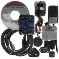
KIT REF DESIGN SENSORLESS BLDC
Manufacturer
Silicon Laboratories Inc
Datasheet
1.SLBLDC-MTR-RD.pdf
(12 pages)
Specifications of SLBLDC-MTR-RD
Main Purpose
Power Management, Motor Control
Embedded
Yes, MCU, 8-Bit
Utilized Ic / Part
C8051F310
Primary Attributes
Brushless DC (BLDC) Motors, 3-Phase, 1A, LIN, SPI, PWM Interface
Secondary Attributes
Potentiometer Speed Control
Processor To Be Evaluated
C8051F310
Interface Type
USB
Lead Free Status / RoHS Status
Contains lead / RoHS non-compliant
Lead Free Status / RoHS Status
Lead free / RoHS Compliant, Contains lead / RoHS non-compliant
Other names
336-1329


5. HyperTerminal Demonstration
Before connecting the USB cable to your computer, make sure you have installed the Reference Design Kit Tools,
including the Virtual COM port driver by following the instructions in Section “4. Reference Design CD Installation”.
Start with the Demo Setup and add a USB cable connection to your computer as shown in Figure 4. The USB
connection is used with a terminal program to provide a basic terminal interface for the Sensorless BLDC motor.
Before opening HyperTerminal, you need to determine which COM port is being used for the Sensorless BLDC
Motor drive. Right-click on My Computer and select “Properties” (see Figure 5 on page 6). This will bring up the
System Properties window. Select the Hardware tab and then click on the Device Manager button. This will bring
up the Device Manager. Expand the Ports (COM & LPT) item. You should see the CP210x USB to UART bridge
controller with the COM port number. Use this COM port number when opening HyperTerminal.
Figure 4. Sensorless BLDC Motor Reference Design Terminal Setup
USB Cable
DEBUG
STOP
START
SENSORLESS-BLDC-MOTOR-RD
SPEED
BLDC Motor
Sensorless
USB
Drive
Rev. 0.3
P1
Sensorless
AC Adapter
BLDC
Motor
5
Related parts for SLBLDC-MTR-RD
Image
Part Number
Description
Manufacturer
Datasheet
Request
R

Part Number:
Description:
SMD/C°/SINGLE-ENDED OUTPUT SILICON OSCILLATOR
Manufacturer:
Silicon Laboratories Inc
Part Number:
Description:
Manufacturer:
Silicon Laboratories Inc
Datasheet:
Part Number:
Description:
N/A N/A/SI4010 AES KEYFOB DEMO WITH LCD RX
Manufacturer:
Silicon Laboratories Inc
Datasheet:
Part Number:
Description:
N/A N/A/SI4010 SIMPLIFIED KEY FOB DEMO WITH LED RX
Manufacturer:
Silicon Laboratories Inc
Datasheet:
Part Number:
Description:
N/A/-40 TO 85 OC/EZLINK MODULE; F930/4432 HIGH BAND (REV E/B1)
Manufacturer:
Silicon Laboratories Inc
Part Number:
Description:
EZLink Module; F930/4432 Low Band (rev e/B1)
Manufacturer:
Silicon Laboratories Inc
Part Number:
Description:
I°/4460 10 DBM RADIO TEST CARD 434 MHZ
Manufacturer:
Silicon Laboratories Inc
Part Number:
Description:
I°/4461 14 DBM RADIO TEST CARD 868 MHZ
Manufacturer:
Silicon Laboratories Inc
Part Number:
Description:
I°/4463 20 DBM RFSWITCH RADIO TEST CARD 460 MHZ
Manufacturer:
Silicon Laboratories Inc
Part Number:
Description:
I°/4463 20 DBM RADIO TEST CARD 868 MHZ
Manufacturer:
Silicon Laboratories Inc
Part Number:
Description:
I°/4463 27 DBM RADIO TEST CARD 868 MHZ
Manufacturer:
Silicon Laboratories Inc
Part Number:
Description:
I°/4463 SKYWORKS 30 DBM RADIO TEST CARD 915 MHZ
Manufacturer:
Silicon Laboratories Inc
Part Number:
Description:
N/A N/A/-40 TO 85 OC/4463 RFMD 30 DBM RADIO TEST CARD 915 MHZ
Manufacturer:
Silicon Laboratories Inc
Part Number:
Description:
I°/4463 20 DBM RADIO TEST CARD 169 MHZ
Manufacturer:
Silicon Laboratories Inc