SLBLDC-MTR-RD Silicon Laboratories Inc, SLBLDC-MTR-RD Datasheet - Page 2
SLBLDC-MTR-RD
Manufacturer Part Number
SLBLDC-MTR-RD
Description
KIT REF DESIGN SENSORLESS BLDC
Manufacturer
Silicon Laboratories Inc
Datasheet
1.SLBLDC-MTR-RD.pdf
(12 pages)
Specifications of SLBLDC-MTR-RD
Main Purpose
Power Management, Motor Control
Embedded
Yes, MCU, 8-Bit
Utilized Ic / Part
C8051F310
Primary Attributes
Brushless DC (BLDC) Motors, 3-Phase, 1A, LIN, SPI, PWM Interface
Secondary Attributes
Potentiometer Speed Control
Processor To Be Evaluated
C8051F310
Interface Type
USB
Lead Free Status / RoHS Status
Contains lead / RoHS non-compliant
Lead Free Status / RoHS Status
Lead free / RoHS Compliant, Contains lead / RoHS non-compliant
Other names
336-1329


SENSORLESS-BLDC-MOTOR-RD
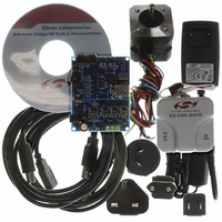
3. Sensorless Motor Reference Design Demonstration
The Sensorless BLDC Motor Reference Design includes everything you need to set up a Sensorless BLDC motor
demonstration. Connect the BLDC motor to the Sensorless BLDC motor control board following the wiring chart for
the Anaheim Automation BLY171S-24V-4000 motor as shown in Table 1.
Connect the 12 V universal ac/dc power adapter to the dc supply (P1) on the Sensorless BLDC Motor Reference
Design Board. Rotate the SPEED knob fully clockwise. Press the START button on the Sensorless BLDC Motor
Reference Design Board. The motor will start running. Notice that the motor will first align and then smoothly speed
up to the minimum closed loop running speed. Rotate the knob counter clockwise to adjust the speed of the motor.
Press the STOP button and the motor will stop spinning.
2
Figure 2. Sensorless BLDC Motor Reference Design Demonstration Setup
DEBUG
STOP
START
Table 1. BLDC Motor Wiring Diagram
Yellow
Color
Black
Red
SPEED
BLDC Motor
Sensorless
Drive
USB
Rev. 0.3
A
B
C
Sensorless
BLDC
Motor
AC Adapter
Location
A
B
C
Related parts for SLBLDC-MTR-RD
Image
Part Number
Description
Manufacturer
Datasheet
Request
R

Part Number:
Description:
SMD/C°/SINGLE-ENDED OUTPUT SILICON OSCILLATOR
Manufacturer:
Silicon Laboratories Inc
Part Number:
Description:
Manufacturer:
Silicon Laboratories Inc
Datasheet:
Part Number:
Description:
N/A N/A/SI4010 AES KEYFOB DEMO WITH LCD RX
Manufacturer:
Silicon Laboratories Inc
Datasheet:
Part Number:
Description:
N/A N/A/SI4010 SIMPLIFIED KEY FOB DEMO WITH LED RX
Manufacturer:
Silicon Laboratories Inc
Datasheet:
Part Number:
Description:
N/A/-40 TO 85 OC/EZLINK MODULE; F930/4432 HIGH BAND (REV E/B1)
Manufacturer:
Silicon Laboratories Inc
Part Number:
Description:
EZLink Module; F930/4432 Low Band (rev e/B1)
Manufacturer:
Silicon Laboratories Inc
Part Number:
Description:
I°/4460 10 DBM RADIO TEST CARD 434 MHZ
Manufacturer:
Silicon Laboratories Inc
Part Number:
Description:
I°/4461 14 DBM RADIO TEST CARD 868 MHZ
Manufacturer:
Silicon Laboratories Inc
Part Number:
Description:
I°/4463 20 DBM RFSWITCH RADIO TEST CARD 460 MHZ
Manufacturer:
Silicon Laboratories Inc
Part Number:
Description:
I°/4463 20 DBM RADIO TEST CARD 868 MHZ
Manufacturer:
Silicon Laboratories Inc
Part Number:
Description:
I°/4463 27 DBM RADIO TEST CARD 868 MHZ
Manufacturer:
Silicon Laboratories Inc
Part Number:
Description:
I°/4463 SKYWORKS 30 DBM RADIO TEST CARD 915 MHZ
Manufacturer:
Silicon Laboratories Inc
Part Number:
Description:
N/A N/A/-40 TO 85 OC/4463 RFMD 30 DBM RADIO TEST CARD 915 MHZ
Manufacturer:
Silicon Laboratories Inc
Part Number:
Description:
I°/4463 20 DBM RADIO TEST CARD 169 MHZ
Manufacturer:
Silicon Laboratories Inc