IRMD2214SS International Rectifier, IRMD2214SS Datasheet - Page 2
IRMD2214SS
Manufacturer Part Number
IRMD2214SS
Description
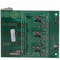
KIT DESIGN EVAL BOARD IR2214SS
Manufacturer
International Rectifier
Series
HVICr
Datasheet
1.IRMD22141SS.pdf
(22 pages)
Specifications of IRMD2214SS
Main Purpose
Power Management, Half H-Bridge Driver (External FET)
Utilized Ic / Part
IR2214SS
Lead Free Status / RoHS Status
Contains lead / RoHS non-compliant
Secondary Attributes
-
Embedded
-
Primary Attributes
-
Other names
*IRMD2214SS


Table of contents
INTRODUCTION .........................................................................................................................................1
BOARD CONNECTORS .............................................................................................................................4
TEST BENCH CONNECTION ....................................................................................................................7
OPERATING DESCRIPTION......................................................................................................................8
BOARD SOLUTIONS................................................................................................................................10
OTHER EXTRA COMPONENTS ..............................................................................................................11
BILL OF MATERIAL .................................................................................................................................15
SCHEMATIC .............................................................................................................................................16
LAYOUT ....................................................................................................................................................16
LAYOUT ....................................................................................................................................................17
Table of figures
Figure 1: TOP image of board .....................................................................................................................4
Figure 2: LED connection ............................................................................................................................5
Figure 3: Test bench connection .................................................................................................................7
Figure 4: Power on sequence......................................................................................................................8
Figure 5: Three phase connection...............................................................................................................9
Figure 6: Example of a desaturation detection event ..................................................................................9
Figure 7: Bootstrap circuit..........................................................................................................................10
Figure 8: Desat external filter ....................................................................................................................11
Figure 9: -V
Figure 10: COM below ground protection..................................................................................................12
Figure 11: Collector-Gate current protection .............................................................................................13
Figure 12: Zener clamp for IGBT gate.......................................................................................................13
www.irf.com
Table of contents......................................................................................................................................2
Table of figures ........................................................................................................................................2
The IR22141SS........................................................................................................................................3
The power module ...................................................................................................................................3
Important Notice.......................................................................................................................................3
Connection with the system controller .....................................................................................................4
FAULT/SD logic signal .............................................................................................................................5
VCC supply pin ........................................................................................................................................5
VSS ground pin (GND).............................................................................................................................5
Connecting the current sensors ...............................................................................................................5
High power signal connector....................................................................................................................6
Connecting the power module .................................................................................................................6
Test Points ...............................................................................................................................................7
Power on sequence .................................................................................................................................8
Normal operating mode............................................................................................................................8
Fault management ...................................................................................................................................8
Multilevel board solution...........................................................................................................................9
Bootstrap circuit .....................................................................................................................................10
Gate resistances ....................................................................................................................................10
Desat circuit ...........................................................................................................................................11
Clamping Diode for Vs below ground ....................................................................................................11
RC filter on com pin................................................................................................................................12
Fast diode between gate and supply pin ...............................................................................................13
Zener diode to preserve the IGBT gate .................................................................................................13
Optional output shunt resistor ................................................................................................................14
Resistor on v
s
clamp ....................................................................................................................................12
cc
........................................................................................................................................14
page
2/22
Datasheet rev 2.1
IRMD22141SS
Sep 9
th
, 2004
Related parts for IRMD2214SS
Image
Part Number
Description
Manufacturer
Datasheet
Request
R

Part Number:
Description:
SCHOTTKY RECTIFIER
Manufacturer:
International Rectifier Corp.
Datasheet:
Part Number:
Description:
SCHOTTKY RECTIFIER
Manufacturer:
International Rectifier Corp.
Datasheet:
Part Number:
Description:
SCHOTTKY RECTIFIER
Manufacturer:
International Rectifier Corp.
Datasheet:
Part Number:
Description:
SCHOTTKY RECTIFIER
Manufacturer:
International Rectifier Corp.
Datasheet:
Part Number:
Description:
SCHOTTKY RECTIFIER
Manufacturer:
International Rectifier Corp.
Datasheet:
Part Number:
Description:
SCHOTTKY RECTIFIER
Manufacturer:
International Rectifier Corp.
Datasheet:
Part Number:
Description:
SCHOTTKY RECTIFIER
Manufacturer:
International Rectifier Corp.
Datasheet:
Part Number:
Description:
SCHOTTKY RECTIFIER
Manufacturer:
International Rectifier Corp.
Datasheet:
Part Number:
Description:
SCHOTTKY RECTIFIER
Manufacturer:
International Rectifier Corp.
Datasheet:
Part Number:
Description:
SCHOTTKY RECTIFIER
Manufacturer:
International Rectifier Corp.
Datasheet:
Part Number:
Description:
SCHOTTKY RECTIFIER
Manufacturer:
International Rectifier Corp.
Datasheet:
Part Number:
Description:
SCHOTTKY RECTIFIER
Manufacturer:
International Rectifier Corp.
Datasheet:
Part Number:
Description:
SCHOTTKY RECTIFIER
Manufacturer:
International Rectifier Corp.
Datasheet:
Part Number:
Description:
SCHOTTKY RECTIFIER
Manufacturer:
International Rectifier Corp.
Datasheet:
Part Number:
Description:
SCHOTTKY RECTIFIER
Manufacturer:
International Rectifier Corp.
Datasheet: