STEVAL-SPMD250V1 STMicroelectronics, STEVAL-SPMD250V1 Datasheet - Page 12
STEVAL-SPMD250V1
Manufacturer Part Number
STEVAL-SPMD250V1
Description
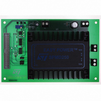
DEMO SYSTEM BASED ON SPMD250STP
Manufacturer
STMicroelectronics
Series
EASY POWER™r
Datasheets
1.STEVAL-SPMD150V2.pdf
(15 pages)
2.STEVAL-SPMD250V2.pdf
(4 pages)
3.STEVAL-SPMD250V1.pdf
(14 pages)
Specifications of STEVAL-SPMD250V1
Main Purpose
Power Management, Motor Control
Embedded
No
Utilized Ic / Part
SPMD250
Primary Attributes
2-Ph Bipolar Stepper Motors
Secondary Attributes
Remote Shutdown
Input Voltage
12 V to 40 V
Maximum Operating Temperature
+ 85 C
Minimum Operating Temperature
- 40 C
Operating Supply Voltage
24 V, 5 V
Product
Power Management Modules
Supply Current
2.5 A
Lead Free Status / RoHS Status
Lead free / RoHS Compliant
Other names
497-9011


5
Note:
12/15
STEVAL-SPMD150V1, STEVAL-SPMD150V2
STEVAL-SPMD150V1, STEVAL-SPMD150V2
To make the boards operative, perform the following simple steps:
●
●
●
●
●
●
●
●
If the internal reference of SPMD150STP is used, connect jumpers JR1, JR2, JR5, JR6; in
this way the motor current is fixed and no more controlled by PractiSPIN™.spmd SW.
Figure 8.
Connect them to the control board by means the 34-wire flat cable and the control
board to the host PC
Connect the stepper motor to P3 and P4 connector
Put jumpers on JR1, JR2, JR3A, JR3B
Apply 5 V to P1 connector
Apply motor voltage VS to P2 connector
Launch the PractiSPIN™.spmd program on the host PC
Click on "connect to ST7 hardware" and perform calibration
–
–
Click done and enter in "speed control mode" or "indexing mode"
Click on calibrate zero and trim R18 on control board until voltage on VREFA and
VREFB is zero.
Click on calibrate max and set the maximum current, corresponding to 100%
current setting in the PractiSPIN™.spmd software, adjusting RV1 (VREFA) and
RV2 (VREFB) trimmers on the target board. The relationship voltage/current is
V = 0.165 I
STEVAL-SPMD150V1 / STEVAL-SPMD150V2 demonstration system
motor
.
Doc ID 15599 Rev 2
AM04226v1
UM0696
Related parts for STEVAL-SPMD250V1
Image
Part Number
Description
Manufacturer
Datasheet
Request
R

Part Number:
Description:
BOARD EVAL FOR MEMS SENSORS
Manufacturer:
STMicroelectronics
Datasheet:

Part Number:
Description:
EVALBOARD/STEVAL-ISV014V1
Manufacturer:
STMicroelectronics
Part Number:
Description:
BOARD EVAL FOR ST802RT1
Manufacturer:
STMicroelectronics
Datasheet:

Part Number:
Description:
BOARD EVAL FOR VACUUM CLEANER
Manufacturer:
STMicroelectronics
Datasheet:

Part Number:
Description:
KIT DEV STARTER ST10F276Z5
Manufacturer:
STMicroelectronics
Datasheet:

Part Number:
Description:
BOARD LED CTLR/DVR STLED316S
Manufacturer:
STMicroelectronics
Datasheet:

Part Number:
Description:
BOARD EVAL BLDC SENSORLESS MOTOR
Manufacturer:
STMicroelectronics
Datasheet:

Part Number:
Description:
BOARD ELECT FISCAL CASH REGISTER
Manufacturer:
STMicroelectronics
Datasheet:

Part Number:
Description:
BOARD EVAL BIPO SOLUTION FOR PFC
Manufacturer:
STMicroelectronics
Datasheet:

Part Number:
Description:
BOARD EVAL UPS 450W VOUT=220V
Manufacturer:
STMicroelectronics
Datasheet:
Part Number:
Description:
STMicroelectronics [RIPPLE-CARRY BINARY COUNTER/DIVIDERS]
Manufacturer:
STMicroelectronics
Datasheet:
Part Number:
Description:
STMicroelectronics [LIQUID-CRYSTAL DISPLAY DRIVERS]
Manufacturer:
STMicroelectronics
Datasheet:
Part Number:
Description:
BOARD EVAL FOR MEMS SENSORS
Manufacturer:
STMicroelectronics
Datasheet: