STEVAL-ISA020V1 STMicroelectronics, STEVAL-ISA020V1 Datasheet - Page 6
STEVAL-ISA020V1
Manufacturer Part Number
STEVAL-ISA020V1
Description
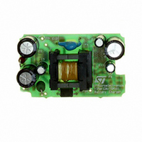
EVAL BOARD 3.5W BATTERY CHARGER
Manufacturer
STMicroelectronics
Type
Battery Managementr
Datasheets
1.VIPER12ADIP-E.pdf
(21 pages)
2.TSM101CDT.pdf
(13 pages)
3.STEVAL-ISA020V1.pdf
(6 pages)
Specifications of STEVAL-ISA020V1
Design Resources
STEVAL-ISA020V1 Gerber Files Battery Charger with TSM101 Bill of Material
Main Purpose
Power Management, Battery Charger
Embedded
No
Utilized Ic / Part
VIPer12AS, TSM101
Primary Attributes
3.5W, 0 ~ 7 V @ 500mA Out, Off-Line
Secondary Attributes
88 ~ 264 VAC
Input Voltage
88 V to 264 V
Output Voltage
0 V to 7 V
Product
Power Management Modules
Silicon Manufacturer
ST Micro
Silicon Core Number
VIPer12AS-E And TSM101
Kit Application Type
Power Management
Application Sub Type
SMPS
Kit Contents
Board
Rohs Compliant
No
Lead Free Status / RoHS Status
Lead free / RoHS Compliant
For Use With/related Products
VIPer12AS-E, TSM101
Other names
497-5519
Available stocks
Company
Part Number
Manufacturer
Quantity
Price
Company:

Part Number:
STEVAL-ISA020V1
Manufacturer:
STMicroelectronics
Quantity:
135


TSM101/A
6/13
Figure 2 : SMPS Using a TL431 as Voltage Controller
The optocoupler current increases and tends to
reduce the output voltage by the way of the PWM
controller.
By enabling the TSM101 current source (pin 2) it
is possible to offset the current sensing by a volt-
age equal to :
Voff # R4 * Io with I
This offset lowers the output charge current and
this function can be used to charge two types of
batteries having different capacities. The current
source is enabled by connecting pin 2 to ground
3 - CALCULATION OF THE ELEMENTS
The charge current is regulated at 700mA (if the
charge control input is left open) or 200mA (if the
charge control input is put to ground ), allowing the
charge of two different types of batteries.
3.1 - Voltage limitation
The end-of- charge voltage is limited at 1.45V/cell,
this is the recommended voltage for an ambient
temperature at 25oC.
A diode is generally inserted at the output of the
charger to avoid the discharge of the battery if the
charger is not powered. This diode is sometimes
directly integrated in the battery pack. The influ-
ence of this diode on the charge is negligible if the
voltage drop (0.7V) is taken into account during
the design of the charger.
The voltage at the output of the charger is :
and regarding R6 and R7 :
V
out
=
R6
----------------------
R6
+
R 7
o
V
r
= 1.4mA
P1, which is a part of R6 and R7 is not considered
in this equation.
The following values are used on the application
board :
battery replaced by a 1k resistor
3.2 - Current regulation
R5 is the sense resistor used for current measure-
ment.
The current regulation is effective when the volt-
age drop across R5 is equal to the voltage on pin
5 of the TSM101 (assuming that the internal cur-
rent source is disabled).
For medium currents (<1A), a voltage drop across
R5 of 200mV = Vr5 is a good value, R5 can be re-
alized with standard low cost 0.5W resistors in
parallel.
parallel)
R2 and R3 can be chosen using the following for-
mula :
CHARGE CONTROL
If the pin 2 is left open, the charge current is nom-
inal at # 700mA.
R6=
R7 = 12k
R6 = 1k
R10 = short circuit
C3 = 100nF
R2 =
R5 =
P1 = 220 , adjust for V
R3
------------------------------- -
Vout Vref
Vr5
--------- -
Ich
Vref
, R5 = 0.285
–
Vref Vr5
--------------------------- -
V r5
–
R7
output
(four 1.2
= 15.2V with the
resistor in
Related parts for STEVAL-ISA020V1
Image
Part Number
Description
Manufacturer
Datasheet
Request
R

Part Number:
Description:
BOARD RGB CTR ST7,STP08C596MTR
Manufacturer:
STMicroelectronics
Datasheet:

Part Number:
Description:
Power Management IC Development Tools Full Speed USB to RS232 Bridge Demo
Manufacturer:
STMicroelectronics
Datasheet:
Part Number:
Description:
Power Management IC Development Tools 2.5W solar eval BRD USB SPV1040 LD39050
Manufacturer:
STMicroelectronics
Datasheet:

Part Number:
Description:
BOARD EVAL FOR MEMS SENSORS
Manufacturer:
STMicroelectronics
Datasheet:

Part Number:
Description:
KIT DEV STARTER ST10F276Z5
Manufacturer:
STMicroelectronics
Datasheet:

Part Number:
Description:
BOARD EVAL HDMI $ VIDEO SWITCH
Manufacturer:
STMicroelectronics
Datasheet:

Part Number:
Description:
BOARD DEMO ACCELEROMETER DIL24
Manufacturer:
STMicroelectronics
Datasheet:

Part Number:
Description:
BOARD STLM75/STDS75/ST72F651
Manufacturer:
STMicroelectronics
Datasheet:

Part Number:
Description:
EVAL BOARD 3AXIS MEMS ACCELLRMTR
Manufacturer:
STMicroelectronics
Datasheet:

Part Number:
Description:
BOARD EVAL 8BIT MICRO + TDE1708
Manufacturer:
STMicroelectronics
Datasheet:
Part Number:
Description:
STMicroelectronics [RIPPLE-CARRY BINARY COUNTER/DIVIDERS]
Manufacturer:
STMicroelectronics
Datasheet:
Part Number:
Description:
STMicroelectronics [LIQUID-CRYSTAL DISPLAY DRIVERS]
Manufacturer:
STMicroelectronics
Datasheet:
Part Number:
Description:
BOARD EVAL FOR MEMS SENSORS
Manufacturer:
STMicroelectronics
Datasheet: