CDB8421 Cirrus Logic Inc, CDB8421 Datasheet - Page 3
CDB8421
Manufacturer Part Number
CDB8421
Description
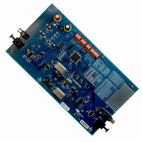
BOARD EVAL FOR CS8421
Manufacturer
Cirrus Logic Inc
Datasheet
1.CDB8421.pdf
(22 pages)
Specifications of CDB8421
Main Purpose
Audio, Sample Rate Converter
Embedded
No
Utilized Ic / Part
CS8421, CS8406, CS8416
Primary Attributes
Sample Rate Converter with Digital Audio Transmitter and Receiver
Secondary Attributes
S/PDIF Interface
Description/function
Audio DSPs
Operating Supply Voltage
3 V to 5 V
Product
Audio Modules
For Use With/related Products
CS8421
Lead Free Status / RoHS Status
Contains lead / RoHS non-compliant
Lead Free Status / RoHS Status
Lead free / RoHS Compliant, Contains lead / RoHS non-compliant
Other names
598-1018


1. SYSTEM OVERVIEW
The CDB8421 demonstration board is an excellent means for evaluating the CS8421 stereo
sample rate converter. Digital audio signal interfaces are provided in the form of S/PDIF receiver
and transmitter and PCM clock/data headers.
The CDB8421 schematic set is shown in Figures 1 through 9 and the board layout is shown in
Figures 10 through 12, and the bill of materials is shown in Table 3.
DS641DB3
1.1
1.2
1.3
A complete description of the CS8421 is included in the CS8421 product data sheet [1], avail-
able online at http://www.cirrus.com
D9 (SRC_UNLOCK) indicates when the SRC is not locked and output from the CS8421 SD-
OUT pin is not valid.
The operation of the CS8406 transmitter and a discussion of the digital audio interface are
included in the CS8406 data sheet [2].
The CS8406 converts the PCM data generated by the CS8421 to the standard S/PDIF data
format. The CS8406 can operate in master or slave mode and accepts 128*Fs, 256*Fs, or
512*Fs master clock on the OMCK input pin. The serial audio input data for the CS8406 is
received from the serial audio output of the CS8421. Digital Interface format selection of I²S
(up to 24-bit), Left Justified (up to 24-bit), or Right Justified (16 or 24-bit) can be made.
S/PDIF output is through J6 or J15.
The operation of the CS8416 receiver (see Figure 3) and a discussion of the digital audio in-
terface are included in the CS8416 data sheet [3].
The CS8416 converts the input S/PDIF data stream into PCM data for the CS8421. The
CS8416 operates in master or slave mode and can output either 128*Fs or 256*Fs from its
RMCK pin. Digital Interface format selection of I²S (24-bit), Left Justified (24-bit), or Right
Justified (16 or 24-bit) can be made.
The CS8416 contains an internal input multiplexer which must be set to receive data from
either the optical input connector (J12) or coaxial input connector (J5). This is done by setting
the appropriate switch on switch-bank S4 to the COAXIAL or OPTICAL position.
D10 (RERR) indicates a receiver error, such as loss of lock.
S/PDIF input is through J5 or J12.
CS8421 Sample Rate Converter
CS8406 Digital Audio Transmitter
CS8416 Digital Audio Receiver
CDB8421
3
Related parts for CDB8421
Image
Part Number
Description
Manufacturer
Datasheet
Request
R

Part Number:
Description:
Development Kit
Manufacturer:
Cirrus Logic Inc
Datasheet:
Part Number:
Description:
Development Kit
Manufacturer:
Cirrus Logic Inc
Datasheet:


Part Number:
Description:
High-efficiency PFC + Fluorescent Lamp Driver Reference Design
Manufacturer:
Cirrus Logic Inc
Datasheet:
Part Number:
Description:
Development Kit
Manufacturer:
Cirrus Logic Inc
Datasheet:
Part Number:
Description:
Development Kit
Manufacturer:
Cirrus Logic Inc
Datasheet:

Part Number:
Description:
Development Kit
Manufacturer:
Cirrus Logic Inc
Datasheet:
Part Number:
Description:
Development Kit
Manufacturer:
Cirrus Logic Inc
Datasheet:
Part Number:
Description:
Development Kit
Manufacturer:
Cirrus Logic Inc
Datasheet:
Part Number:
Description:
Development Kit
Manufacturer:
Cirrus Logic Inc
Datasheet:

Part Number:
Description:
EVALUATION BOARD FOR CS8427
Manufacturer:
Cirrus Logic Inc
Datasheet:

Part Number:
Description:
BOARD EVAL FOR CS8416 RCVR
Manufacturer:
Cirrus Logic Inc
Datasheet:

Part Number:
Description:
EVALUATION BOARD FOR CS8420
Manufacturer:
Cirrus Logic Inc
Datasheet:

Part Number:
Description:
KIT DEVELOPMENT EP9315 ARM9
Manufacturer:
Cirrus Logic Inc
Datasheet:

Part Number:
Description:
KIT DEVELOPMENT EP9302 ARM9
Manufacturer:
Cirrus Logic Inc
Datasheet: