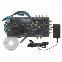
AD9520-1/PCBZ Analog Devices Inc, AD9520-1/PCBZ Datasheet - Page 69

AD9520-1/PCBZ
Manufacturer Part Number
AD9520-1/PCBZ
Description
BOARD EVAL FOR AD9520-1
Manufacturer
Analog Devices Inc
Specifications of AD9520-1/PCBZ
Design Resources
Synchronizing Multiple AD9910 1 GSPS Direct Digital Synthesizers (CN0121) Phase Coherent FSK Modulator (CN0186)
Main Purpose
Timing, Clock Generator
Embedded
No
Utilized Ic / Part
AD9520-1
Primary Attributes
12 LVPECL/24 CMOS Output Clock Generator with 2.5 GHz VCO
Secondary Attributes
SPI and I2C Compatible Control Port
Silicon Manufacturer
Analog Devices
Application Sub Type
PLL Clock Synthesizer
Kit Application Type
Clock & Timing
Silicon Core Number
AD9520-0, AD9520-2, AD9520-2
Silicon Family Name
AD9520-X
Rohs Compliant
Yes
Lead Free Status / RoHS Status
Lead free / RoHS Compliant
Reg.
Addr
(Hex) Bit(s) Name
016
016
017
[3]
[2:0] Prescaler P
[7:2] STATUS
B counter
bypass
pin control
Description
B counter bypass. This is only valid when operating the prescaler in FD mode.
[3] = 0; normal (default).
[3] = 1; B counter is set to divide-by-1. This allows the prescaler setting to determine the divide for
the N divider.
Prescaler: DM = dual modulus and FD = fixed divide. The Prescaler P is part of the feedback divider.
[2]
0
0
0
0
1
1
1
1
Selects the signal that appears at the STATUS pin. 0x01D[7] must be 0 to reprogram the STATUS pin.
[7]
0
0
0
0
0
0
0
0
1
1
1
1
1
1
1
1
1
1
1
1
1
1
1
1
1
1
1
1
[1]
0
0
1
1
0
0
1
1
[6] [5] [4]
0
0
0
0
0
0
0
X
0
0
0
0
0
0
0
0
0
0
0
0
0
0
0
0
1
1
1
1
0
0
0
0
0
0
0
X
0
0
0
0
0
0
0
0
1
1
1
1
1
1
1
1
0
0
0
0
[0] Mode
0
1
0
1
0
1
0
1
0
0
0
0
1
1
1
X
0
0
0
0
1
1
1
1
0
0
0
0
1
1
1
1
0
0
0
0
FD
FD
DM
DM
DM
DM
DM
FD
[3]
0
0
1
1
0
0
1
X
0
0
1
1
0
0
1
1
0
1
1
0
0
1
1
0
1
1
0
0
Rev. 0 | Page 69 of 84
1
0
1
1
Prescaler
Divide-by-1.
Divide-by-2.
Divide-by-2 and divide-by-3 when A ≠ 0; divide-by-2 when A = 0.
Divide-by-4 and divide-by-5 when A ≠ 0; divide-by-4 when A = 0.
Divide-by-8 and divide-by-9 when A ≠ 0; divide-by-8 when A = 0.
Divide-by-16 and divide-by-17 when A ≠ 0; divide-by-16 when A = 0.
Divide-by-32 and divide-by-33 when A ≠ 0; divide-by-32 when A = 0 (default).
Divide-by-3.
[2]
0
1
0
1
0
1
0
X
0
1
0
1
0
1
0
1
0
1
0
1
0
1
0
0
Level or
Dynamic
Signal
LVL
DYN
DYN
DYN
DYN
DYN
DYN
LVL
LVL
DYN
DYN
DYN
DYN
LVL
LVL
LVL
LVL
LVL
LVL
LVL
LVL
LVL
LVL
LVL
LVL
DYN
DYN
DYN
Signal at STATUS Pin
Ground, dc (default).
N divider output (after the delay).
R divider output (after the delay).
A divider output.
Prescaler output.
PFD up pulse.
PFD down pulse.
Ground (dc); for all other cases of 0XXXXX not specified.
The selections that follow are the same as for REFMON.
Ground (dc).
REF1 clock (differential reference when in differential mode).
REF2 clock (N/A in differential mode).
Selected reference to PLL (differential reference when in
differential mode).
Unselected reference to PLL (not available in differential
mode).
Status of selected reference (status of differential reference);
active high.
Status of unselected reference (not available in differential
mode); active high.
Status REF1 frequency (active high).
Status REF2 frequency (active high).
(Status REF1 frequency) AND (status REF2 frequency).
(DLD) AND (status of selected reference) AND (status of VCO).
Status of VCO frequency (active high).
Selected reference (low = REF1, high = REF2).
DLD; active high.
Holdover active (active high).
LD pin comparator output (active high).
VS (PLL power supply).
REF1 clock (differential reference when in differential mode).
REF2 clock (not available in differential mode).
Selected reference to PLL (differential reference when in
differential mode).
AD9520-1


