ADNK-3083 Avago Technologies US Inc., ADNK-3083 Datasheet - Page 19
ADNK-3083
Manufacturer Part Number
ADNK-3083
Description
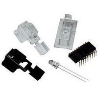
KIT REFERENCE DESIGN ADNS-3080
Manufacturer
Avago Technologies US Inc.
Specifications of ADNK-3083
Main Purpose
Reference Design, Optical Mouse
Utilized Ic / Part
ADNS-3080, CY7C63743-PXC, CY7C63743A
Kit Contents
ADNS-3080 Sensor, UP, Hardware And Documentation
Peak Reflow Compatible (260 C)
Yes
Tool / Board Applications
Optical Mouse Sensors
Description/function
Optical Mouse Sensor Kit
Interface Type
USB
Product
Display Modules
Touch Panel
No Touch Panel
Development Tool Type
Hardware / Software - Dev Kit (Dev Tool)
Rohs Compliant
Yes
For Use With
ADNS-3080
Lead Free Status / RoHS Status
Lead free / RoHS Compliant
Secondary Attributes
-
Embedded
-
Primary Attributes
-
Lead Free Status / Rohs Status
Details
For Use With/related Products
CY7C63743-PXC, CY7C63743A-PC
Lead Free Status / RoHS Status
Lead free / RoHS Compliant, Lead free / RoHS Compliant


The PS/2 specification calls out the following default mouse report format. Byte 0 is the button data (1=pressed, 0=re-
leased), X and Y optics sign bits, and X and Y overflow bits. Byte 1 is the X optics data in 2’s complement format. Byte 2
has the Y optics data in 2’s complement format. At reset or power-on the standard PS/2 reporting format is enabled.
Byte 0
Byte 1
Byte 2
After the following sequence of commands, the wheel report format is enabled.
0xF3, 0xC8
0xF3, 0x64
0xF3, 0x32
0xF2, 0x03
After the Read Device Type command returns 0x03 to indicate that this is a Microsoft compatible three button-wheel
mouse, the wheel report format is enabled. After this initialization sequence, the PS/2 wheel reporting format is
enabled. The fourth byte represents the wheel data. This byte is assigned 0x01 for forward wheel movement and 0xFF
for backward wheel movement. When the wheel is idle, this value is 0x00.
Byte 0
Byte 1
Byte 2
Byte 3
The PS2 data transmission according to the PS/2 Hardware Interface Technical Reference including eleven bits for
each byte sent. The bits are sent in the following order with data valid on the falling edge of the clock. See the PS/2
Hardware Interface Technical Reference manual for timing information.
Start Bit
(Always 0)
1
Data
Bit 0
Bit 7
Y Overflow X Overflow Y sign
X
Y
Bit 7
Y Overflow X Overflow Y sign
X
Y
Wheel*
Set Sampling Rate 200 per second
Set Sampling Rate 100 per second
Set Sampling Rate 50 per second
Read Device Type returns a value of 0x03
Data
Bit 1
X
Y
X
Y
Wheel*
Data
Bit 2
X
Y
X
Y
Wheel*
Data
Bit 3
X sign
X
Y
X sign
X
Y
Wheel*
Data
Bit 4
Data
Bit 5
Reserved 0 Reserved 0 Right button Left button
X
Y
Always 1
X
Y
Wheel*
Data
Bit 6
X
Y
Middle Button
X
Y
Wheel*
Data Bit 7
Bit 6
X
Y
X
Y
Wheel*
Odd
Parity Bit
Bit 0
X
Y
Bit 0
Right Left
button button
X
Y
Wheel*
Stop Bit
(Always 1)
Related parts for ADNK-3083
Image
Part Number
Description
Manufacturer
Datasheet
Request
R

Part Number:
Description:
ADNK-3000 Sample Kit
Manufacturer:
Avago Technologies US Inc.
Datasheet:

Part Number:
Description:
KIT REFERENCE DESIGN ADNK-3060
Manufacturer:
Avago Technologies US Inc.
Datasheet:

Part Number:
Description:
KIT REFERENCE DESIGN ADNK-5030
Manufacturer:
Avago Technologies US Inc.
Datasheet:
Part Number:
Description:
KIT DES BLUETOOTH OPT ADNK-3043
Manufacturer:
Avago Technologies US Inc.
Datasheet:
Part Number:
Description:
KIT SAMPLE FOR ADNS-5030
Manufacturer:
Avago Technologies US Inc.
Datasheet:
Part Number:
Description:
KIT SAMPLE OPT MOUSE ADNS-3550
Manufacturer:
Avago Technologies US Inc.
Datasheet:
Part Number:
Description:
KIT SAMPLE OPT MOUSE ADNS-5000
Manufacturer:
Avago Technologies US Inc.
Datasheet:

Part Number:
Description:
KIT SAMPLE OPTICAL MOUSE A5050
Manufacturer:
Avago Technologies US Inc.
Datasheet:
Part Number:
Description:
KIT SAMPLE OPT MOUSE ADNS-5060
Manufacturer:
Avago Technologies US Inc.
Datasheet:

Part Number:
Description:
OPTOCOUPLER GATE DRV 2A 16-SOIC
Manufacturer:
Avago Technologies US Inc.
Datasheet:
Part Number:
Description:
OPTOCOUPLER 2CH 2.5A 16-SOIC
Manufacturer:
Avago Technologies US Inc.
Datasheet:

Part Number:
Description:
OPTOCOUPLER GATE DRV 0.4A 16SOIC
Manufacturer:
Avago Technologies US Inc.
Datasheet:

Part Number:
Description:
OPTOCOUPLER 2.0A 250KHZ 8-DIP
Manufacturer:
Avago Technologies US Inc.
Datasheet:

Part Number:
Description:
OPTOCOUPLER 2.0A 250KHZ GW 8-SMD
Manufacturer:
Avago Technologies US Inc.
Datasheet: