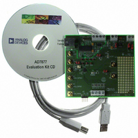
EVAL-AD7877EBZ Analog Devices Inc, EVAL-AD7877EBZ Datasheet - Page 3

EVAL-AD7877EBZ
Manufacturer Part Number
EVAL-AD7877EBZ
Description
BOARD EVALUATION FOR AD7877
Manufacturer
Analog Devices Inc
Datasheets
1.AD7877ACBZ-REEL7.pdf
(44 pages)
2.EVAL-AD7877EBZ.pdf
(16 pages)
3.EVAL-AD7877EBZ.pdf
(44 pages)
Specifications of EVAL-AD7877EBZ
Main Purpose
Interface, Touch Screen Controller
Embedded
No
Utilized Ic / Part
AD7877
Primary Attributes
4-Wire Resistive Touch Screen Controller, SPI Interface, On-Chip: Temp Sensor, Voltage Reference, 8-Bit DAC
Secondary Attributes
USB GUI, LCD Noise Reduction Feature, 2.7 ~ 5.25 V, Wake Up on Touch Feature
Lead Free Status / RoHS Status
Lead free / RoHS Compliant
Number
J5
J4
J3
J2
Number
LK1
LK2
LK3
LK4
LK5
LK6
Number
D1
D2
D3
Purchase of licensed I
Patent Rights to use these components in an I
REV. Sp0
2
C components of Analog Devices or on of its sublicensed Associated Companies conveys a license for the purchaser under the Philips I
BAT2 Input
STOPACQ Input
Name
AUX3/GPIO3
BAT1
BAT2
Touch Screen
Name
V
A
V
Input Power
Name
PENIRQ Green
DAV Green
Power Green
DRIVE
RNG
REF
Input
Input
2
C system, provided that the system conforms to the I
INDICATOR LED FUNCTION DESCRIPTIONS
Description
This subminiature BNC socket can be used to apply a signal to the AUX3/GPIO3
input on the AD7877.
This subminiature BNC socket can be used to apply a signal to the BAT1 input on
the AD7877.
This subminiature BNC socket can be used to apply a signal to the BAT2 input on
the AD7877. Link 1 must be in the A position for this connector to be linked to
the AD7877.
This connector can be used to connect a touch screen to the AD7877 and should be
connected as follows: J2-1 to X–, J2-2 to Y–, J2-3 to X+, and J2-4 to Y+.
Description
This jumper selects the input signal to the BAT2 input of the AD7877. If the jumper is
in Position A, BAT2 is connected to Connector J3. An input voltage signal can then be
applied to J3. If the link is in Position B, BAT2 is connected to a variable resistor, R1.
The user can vary R1 to change the input voltage on BAT2. The maximum resistance
of R1 is 2 k .
This jumper selects the input signal to the V
is in Position A, 3.3 V is connected to V
J15-2 is connected to V
If this jumper is in Position A, A
DAC on the AD7877 is in voltage mode, the link should be in this position.
If the jumper is in Position B, A
the DAC on the AD7877 is in current mode, the link should be in this position.
Resistor R9 sets the output range for the DAC in current mode.
This jumper selects the input signal to the V
in Position A, 3.3 V is connected to V
J15-1 is connected to V
left open or in Position B with J15-1 left floating.
This jumper selects the input power for the evaluation board. If the jumper is in
Position A, power for the board must be supplied through Connector J13. If the link is
in Position B, the USB connection supplies the power for the board.
This jumper selects the input signal to the STOPACQ pin. If the jumper is in
Position A, the pin is tied to GND. If the link is in Position B, it is connected to J9.
STOPACQ should not be left floating at any time; either a signal should be applied
to J9 or the pin tied.
Description
This LED indicates when lit that the PENIRQ interrupt on the AD7877 is active.
This LED indicates when lit that the DAV interrupt on the AD7877 is active.
This LED indicates when lit that the evaluation board is powered.
LINK FUNCTION DESCRIPTIONS
–3–
DRIVE
REF
. If the internal reference is used, the jumper must be either
.
RNG
RNG
2
C Standard Specification as defined by Philips.
is connected through Resistor R9 to GND. When
on the AD7877 is connected to GND. When the
REF
DRIVE
. If the jumper is in Position B, Connector
REF
DRIVE
. If the jumper is in Position B, Connector
input of the AD7877. If the jumper is
input of the AD7877. If the jumper
EVAL-AD7877
2
C


