OM6277,598 NXP Semiconductors, OM6277,598 Datasheet - Page 18
OM6277,598
Manufacturer Part Number
OM6277,598
Description
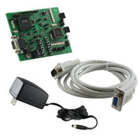
DEMO BOARD FOR PCA9564
Manufacturer
NXP Semiconductors
Datasheet
1.OM6277598.pdf
(52 pages)
Specifications of OM6277,598
Main Purpose
Interface, I2C Controller
Embedded
Yes, MCU, 8-Bit
Utilized Ic / Part
PCA9564
Primary Attributes
I2C Bus Controller, 1 8-Bit GPIO, 1 8-Bit LED Dimmer
Secondary Attributes
8 Momentary Switches, 23 LEDs
Lead Free Status / RoHS Status
Not applicable / Not applicable
Other names
568-4001
935283226598
935283226598


Source Code P89LV51RD2 – Rev 1.0
P89LV51RD2/PCA9564 source code of the embedded software is organized in several files written in C language.
Modularity of the files allows building applications using an 8051-core microcontroller and a PCA9564 in an easy and
intuitive way. Most of the files are core independent and can be used with different types of microcontrollers. Only the
file generating the control signals and receiving/transmitting data is subject to modification depending on the type of
microcontroller used.
The code in C language is divided in several files, organized as following:
1. I2CEXPRT.H:
2. Contains the definition of the different structures and functions used in the code.
3. Mainloop.c:
4. I2C_Routines.c and I2C_Routines.h:
5. I2CDRIVR.C and I2CDRIVR.H:
6. I2CMASTR.C and I2CMASTR.h:
7. I2CINTFC.C:
8. PCA9564sys.c and PCA9564sys.h:
9. Interrupts.c:
Complete source code can be found in Appendix 1 “P89LV51RD2 Microcontroller Source Code – Rev1.0”.
Source Code P89LPC932 – Rev 1.0
P89LPC932 microcontroller is used as a slave device with the default embedded programs and use only the slave part of
the I
1. main.c:
Contain the different programs selectable by the user. These files are generally those that need to be modified in
order to develop specific programs or functions. Main functions are:
-
-
-
-
-
Contains the main running loop:
-
-
Handle the selection between master and slave mode.
Contain the functions handling the Master Transmitter and Master Receiver modes. Handle the different states of
the state machine and generate the sequencing of the commands based upon the previous command and the status
information. Interface directly with the PCA9564 (read and write in a specific register)
Contains the description of the top functions used to send and receive I
-
-
-
-
Contain the actual interface between the microcontroller and the PCA9564: control signal generation, data writing
and reading. This file is specific to an 8051-type microcontroller and needs to be changed if another type of
microcontroller is used to interface with the PCA9564.
Contains the definition of the Interrupts – Not used in this program – For future reference
2
Contains the instructions to interface with the P89LV51RD2/PCA9564 default embedded program:
a) Instruction controlling LD[13:20]: S – Address+W – 0x00 – Data[7:0] – P
b) Instruction controlling the “I
c) Instruction allowing reading back the I
C core.
void Blinker_Up_Down(void): Function for Program 1
void ReadEEprom(short int MinEEPtr, short int MaxEEPtr, int Operation_EEprom, int Operation_Function)
and void Preset_Patterns_PCA9532(void): Functions for Program 2
void LV51_LPC932(void): Function for Program 3
unsigned char Search_Routine(unsigned char min, unsigned char max) and void I2C_Address_Search(void):
Functions for Program 4
void GPIO_Interrupt_Handler(void): Function handling actions on pushbuttons S1 to S8
-
-
Initialization at power up or reset
Call to the function handling the program selection
Start, Write, Stop
Start, Read, Stop
Start, Write, Repeated Start, Read, Stop
Start, Write, Repeated Start, Write, Stop
with Data = I
Data[0] = state LD13
Data[7] = state LD20
2
C slave address
2
C address Scan and Memorize” procedure: S – Address+W – 0xEE – P
2
C slave address: S – Address+W – 0xFF – Sr – Address+R – Data – P
18
2
C messages:
Related parts for OM6277,598
Image
Part Number
Description
Manufacturer
Datasheet
Request
R

Part Number:
Description:
Display Modules & Development Tools I2C BUS CONTROLLER EVAL BOARD
Manufacturer:
NXP Semiconductors

Part Number:
Description:
NXP Semiconductors designed the LPC2420/2460 microcontroller around a 16-bit/32-bitARM7TDMI-S CPU core with real-time debug interfaces that include both JTAG andembedded trace
Manufacturer:
NXP Semiconductors
Datasheet:

Part Number:
Description:
NXP Semiconductors designed the LPC2458 microcontroller around a 16-bit/32-bitARM7TDMI-S CPU core with real-time debug interfaces that include both JTAG andembedded trace
Manufacturer:
NXP Semiconductors
Datasheet:
Part Number:
Description:
NXP Semiconductors designed the LPC2468 microcontroller around a 16-bit/32-bitARM7TDMI-S CPU core with real-time debug interfaces that include both JTAG andembedded trace
Manufacturer:
NXP Semiconductors
Datasheet:
Part Number:
Description:
NXP Semiconductors designed the LPC2470 microcontroller, powered by theARM7TDMI-S core, to be a highly integrated microcontroller for a wide range ofapplications that require advanced communications and high quality graphic displays
Manufacturer:
NXP Semiconductors
Datasheet:
Part Number:
Description:
NXP Semiconductors designed the LPC2478 microcontroller, powered by theARM7TDMI-S core, to be a highly integrated microcontroller for a wide range ofapplications that require advanced communications and high quality graphic displays
Manufacturer:
NXP Semiconductors
Datasheet:
Part Number:
Description:
The Philips Semiconductors XA (eXtended Architecture) family of 16-bit single-chip microcontrollers is powerful enough to easily handle the requirements of high performance embedded applications, yet inexpensive enough to compete in the market for hi
Manufacturer:
NXP Semiconductors
Datasheet:
Part Number:
Description:
The XA-S3 device is a member of Philips Semiconductors? XA(eXtended Architecture) family of high performance 16-bitsingle-chip microcontrollers
Manufacturer:
NXP Semiconductors
Datasheet:

Part Number:
Description:
The NXP BlueStreak LH75401/LH75411 family consists of two low-cost 16/32-bit System-on-Chip (SoC) devices
Manufacturer:
NXP Semiconductors
Datasheet:
Part Number:
Description:
The NXP LPC3130/3131 combine an 180 MHz ARM926EJ-S CPU core, high-speed USB2
Manufacturer:
NXP Semiconductors
Datasheet:
Part Number:
Description:
The NXP LPC3141 combine a 270 MHz ARM926EJ-S CPU core, High-speed USB 2
Manufacturer:
NXP Semiconductors
Part Number:
Description:
The NXP LPC3143 combine a 270 MHz ARM926EJ-S CPU core, High-speed USB 2
Manufacturer:
NXP Semiconductors

Part Number:
Description:
The NXP LPC3152 combines an 180 MHz ARM926EJ-S CPU core, High-speed USB 2
Manufacturer:
NXP Semiconductors
Part Number:
Description:
The NXP LPC3154 combines an 180 MHz ARM926EJ-S CPU core, High-speed USB 2
Manufacturer:
NXP Semiconductors