ATA6622-EK Atmel, ATA6622-EK Datasheet - Page 5
ATA6622-EK
Manufacturer Part Number
ATA6622-EK
Description
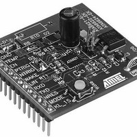
BOARD DEMO LIN SBC FOR ATA6622
Manufacturer
Atmel
Specifications of ATA6622-EK
Main Purpose
Interface, LIN
Embedded
Yes, MCU, 8-Bit
Utilized Ic / Part
ATA6622
Primary Attributes
LIN-SBC (System-Basis-Chip) Transceiver, LIN 2.0, Voltage Regulator, Window Watchdog
Secondary Attributes
4 Power Modes: Pre-Normal, Normal, Sleep, Silent, 20-QFN
Lead Free Status / RoHS Status
Contains lead / RoHS non-compliant


3.7
3.8
3.9
3.10
3.11
3.12
4986J–AUTO–03/11
Input/Output Pin (TXD)
TXD Dominant Time-out Function
Output Pin (RXD)
Enable Input Pin (EN)
Wake Input Pin (WAKE)
Mode Input Pin (MODE)
In Normal Mode the TXD pin is the microcontroller interface used to control the state of the LIN
output. TXD must be pulled to ground in order to have a low LIN-bus. If TXD is high or uncon-
nected (internal pull-up resistor), the LIN output transistor is turned off, and the bus is in
recessive state. During Fail-safe Mode, this pin is used as output. It is current-limited to <
8mA. and is latched to low if the last wake-up event was from pin WAKE or KL_15.
The TXD input has an internal pull-up resistor. An internal timer prevents the bus line from
being driven permanently in dominant state. If TXD is forced to low for longer than t
the LIN-bus driver is switched to recessive state.
To reactivate the LIN bus driver, switch TXD to high (> 10µs).
The time-out function is disabled in the ATA6626. Switching to dominant level on the LIN bus
occurs without any time limitations.
This output pin reports the state of the LIN-bus to the microcontroller. LIN high (recessive
state) is reported by a high level at RXD; LIN low (dominant state) is reported by a low level at
RXD. The output has an internal pull-up resistor with typically 5k to VCC. The AC character-
istics can be defined with an external load capacitor of 20pF.
The output is short-circuit protected. RXD is switched off in Unpowered Mode (i.e., V
The Enable Input pin controls the operation mode of the device. If EN is high, the circuit is in
Normal Mode, with transmission paths from TXD to LIN and from LIN to RXD both active. The
VCC voltage regulator operates with 3.3V/5V/85mA output capability.
If EN is switched to low while TXD is still high, the device is forced to Silent Mode. No data
transmission is then possible, and the current consumption is reduced to I
VCC regulator has its full functionality.
If EN is switched to low while TXD is low, the device is forced to Sleep Mode. No data trans-
mission is possible, and the voltage regulator is switched off.
The Wake Input pin is a high-voltage input used to wake up the device from Sleep Mode or
Silent Mode. It is usually connected to an external switch in the application to generate a local
wake-up. A pull-up current source, typically 10µA, is implemented.
If a local wake-up is not needed in the application, connect the Wake pin directly to the VS pin.
Connect the MODE pin directly or via an external resistor to GND for normal watchdog opera-
tion. To debug the software of the connected microcontroller, connect MODE pin to 3.3V/5V
and the watchdog is switched off.
Atmel ATA6622/ATA6624/ATA6626
VS
typ. 57µA. The
DOM
S
= 0V).
> 6ms,
5
Related parts for ATA6622-EK
Image
Part Number
Description
Manufacturer
Datasheet
Request
R

Part Number:
Description:
TXRX LIN BUS REG WATCHDOG 20-QFN
Manufacturer:
Atmel
Datasheet:
Part Number:
Description:
TXRX LIN BUS REG WATCHDOG 20-QFN
Manufacturer:
Atmel
Datasheet:

Part Number:
Description:
LIN Bus Transceiver with 3.3V (5V) Regulator and Watchdog
Manufacturer:
ATMEL Corporation
Datasheet:
Part Number:
Description:
(ATA6622 - ATA6626) LIN Bus Transceiver
Manufacturer:
ATMEL Corporation
Datasheet:

Part Number:
Description:
DEV KIT FOR AVR/AVR32
Manufacturer:
Atmel
Datasheet:
Part Number:
Description:
INTERVAL AND WIPE/WASH WIPER CONTROL IC WITH DELAY
Manufacturer:
ATMEL Corporation
Datasheet:
Part Number:
Description:
Low-Voltage Voice-Switched IC for Hands-Free Operation
Manufacturer:
ATMEL Corporation
Datasheet:
Part Number:
Description:
MONOLITHIC INTEGRATED FEATUREPHONE CIRCUIT
Manufacturer:
ATMEL Corporation
Datasheet:
Part Number:
Description:
AM-FM Receiver IC U4255BM-M
Manufacturer:
ATMEL Corporation
Datasheet:
Part Number:
Description:
Monolithic Integrated Feature Phone Circuit
Manufacturer:
ATMEL Corporation
Datasheet:
Part Number:
Description:
Multistandard Video-IF and Quasi Parallel Sound Processing
Manufacturer:
ATMEL Corporation
Datasheet:
Part Number:
Description:
High-performance EE PLD
Manufacturer:
ATMEL Corporation
Datasheet: