MXSIGDM Microchip Technology, MXSIGDM Datasheet - Page 17
MXSIGDM
Manufacturer Part Number
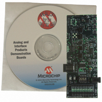
MXSIGDM
Description
BOARD DEMO PICTAIL MIXED SIGNAL
Manufacturer
Microchip Technology
Series
PICtail™r
Datasheet
1.MXSIGDM.pdf
(54 pages)
Specifications of MXSIGDM
Main Purpose
Mixed Signal for MCU: ADC, DAC,
Embedded
Yes, MCU, 8-Bit
Utilized Ic / Part
TX132x,MCP330x,320x,494x,3221,3201,1525,1541
Primary Attributes
3 ADCs, 3 DACs, 2 Voltage References, 5V LDO
Secondary Attributes
DIP Switches, 2 LEDs, PIC16F767
Processor To Be Evaluated
TC132x, MCP330x, MCP320x, MCP492x, MCP3221, MCP3021, MCP15x
Interface Type
I2C, SPI
Lead Free Status / RoHS Status
Contains lead / RoHS non-compliant
Lead Free Status / RoHS Status
Lead free / RoHS Compliant, Contains lead / RoHS non-compliant


2004 Microchip Technology Inc.
2.3.2
The Mixed Signal PICtail™ Demo Board firmware utilizes PICmicro
assembly language, Microchip MPASM™ assembler and MPLINK™ linker to build
the.HEX machine file. MixedSignal_v100.asm, DAC_dtmf.asm, p16F767.inc
and MCP492X_16f767i.lkr files are needed in your project to build the
MixedSignalPICtail.hex.
MixedSignal_v100.asm contains the main program and most of the subroutines.
After initialization of critical PICmicro microcontroller peripherals (including the internal
oscillator to 8 Mhz), the main loop polls the four DIP switches to determine the selected
mode of operation. The DIP switches create a 4-bit binary number from 0 to 15. If a
change of mode is detected for 100 ms during 500 ms of scanning, a new mode is
selected and the LEDs are alternately flashed for two seconds. Most of the modes will
time-out and re-scan the DIP switches periodically.
Refer to Appendix C. “MixedSignal_V100.asm Description” for the commented
source code further describing each mode.
Modes 0XXX primarily utilize the MCP492X DAC modes:
1. Mode0000: Use the DTMF generation subroutine (located in DAC_dtmf.asm)
2. Mode0001: Send 000h and FFFh commands to generate a 100 Hz R-R output
3. Mode0010: Send 400h and BFFh commands to generate a 100 Hz output on the
4. Mode0011: DACA = SHDN, DACB = SHDN, PIC = SLEEP. This mode demon-
5. Mode0100: DACB and DACA = 800h and Read w/PIC16F767 10b ADC, “broad-
6. Mode0101: DACB = 801h, DACA = 800h and Read w/MCP3302 13b Dif, “broad-
7. Mode0110: DACB and DACA = 800h and Read w/MCP3551, “broadcast on
8. Mode0111: Open for user to define their own routine.
to dial a phone number stored in memory. Analyze output on V
SMA connector. See Appendix F. “DTMF Scope Captures” for resulting
waveform frequency analysis.
on the MCP492X. Probe V
MCP492X. Probe V
strates the low-power nature of the DAC, the PICmicro microcontroller, the op
amp and the LDO. A power cycle is required after the mode switch is changed to
exit this mode.
cast on USART”. This mode is useful for evaluating the PICmicro microcontroller’s
ADC. A
analyzed through the 19200 baud async, 9-bit transmission. Microchip’s Data
View analysis tool, along with the MCP3551 USB evaluation board, provide a
“canned” analysis solution.
cast on USART”. This mode is useful for evaluating the MCP3302 or the
MCP3204 ADC. A
can be analyzed through the 19200 baud async, 9-bit transmission. Microchip’s
Data View analysis tool, along with the MCP3551 USB evaluation board, provide
a “canned” analysis solution.
USART”. This mode is useful for evaluating the MCP3551 ADC or the MCP1541
V
analyzed through the 19200 baud async, 9-bit transmission. Microchip’s Data
View analysis tool, along with the MCP3551 USB evaluation board, provide a
“canned” analysis solution.
REF
. A
The Embedded System Firmware
IN_B
IN_B
can be injected with an alternative signal and the result can be
can be injected with an alternative signal and the result can be
IN_B
OUTA
can be injected with an alternative signal and the result
and V
OUTA
OUTB
and V
to see the resulting waveforms.
OUTB
to see the resulting waveforms.
OUTB
®
microcontroller
DS51523A-page 13
or V
OUTD
’s
Related parts for MXSIGDM
Image
Part Number
Description
Manufacturer
Datasheet
Request
R

Part Number:
Description:
Manufacturer:
Microchip Technology Inc.
Datasheet:
Part Number:
Description:
Manufacturer:
Microchip Technology Inc.
Datasheet:
Part Number:
Description:
Manufacturer:
Microchip Technology Inc.
Datasheet:
Part Number:
Description:
Manufacturer:
Microchip Technology Inc.
Datasheet:
Part Number:
Description:
Manufacturer:
Microchip Technology Inc.
Datasheet:
Part Number:
Description:
Manufacturer:
Microchip Technology Inc.
Datasheet:
Part Number:
Description:
Manufacturer:
Microchip Technology Inc.
Datasheet:
Part Number:
Description:
Manufacturer:
Microchip Technology Inc.
Datasheet: