MCP2150DM Microchip Technology, MCP2150DM Datasheet - Page 7
MCP2150DM
Manufacturer Part Number
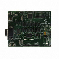
MCP2150DM
Description
BOARD DEMO FOR MCP2150
Manufacturer
Microchip Technology
Specifications of MCP2150DM
Main Purpose
Interface, IrDA
Embedded
Yes, MCU, 8-Bit
Utilized Ic / Part
MCP2150
Primary Attributes
IrDA Controller with PIC18F MCU
Secondary Attributes
USB Interface
Processor To Be Evaluated
MCP2150, MCP2155
Processor Series
MCP215x
Interface Type
USB
Lead Free Status / RoHS Status
Lead free / RoHS Compliant
Lead Free Status / RoHS Status
Lead free / RoHS Compliant, Lead free / RoHS Compliant


2.0
The MCP2150 is a cost effective, low pin count (18-
pin), easy to use device for implementing IrDA stan-
dard wireless connectivity. The MCP2150 provides
support for the IrDA standard protocol “stack” plus bit
encoding/decoding. The Serial interface and IR baud
rates are independantly selectable.
2.1
Any time the device is powered up
the Power Up Timer delay
lowed by an Oscillator Start-up Timer (OST) delay
(parameter
nication with the device may be initiated. This commu-
nication is from both the infrared transceiver’s side as
well as the controller’s UART interface.
2.2
The MCP2150 is forced into the reset state when the
RESET pin is in the low state. Once the RESET pin is
brought to a high state, the Device Reset sequence
occurs. Once the sequence completes, functional
operation begins.
2.3
The MCP2150 requires a clock source to operate. The
frequency of this clock is 11.0592 MHz (electrical spec-
ification
either a crystal/resonator or as an external clock input.
2.3.1
A crystal or ceramic resonator can be connected to the
OSC1 and OSC2 pins to establish oscillation
(Figure
the use of a parallel cut crystal. Use of a series cut crys-
tal may give a frequency outside of the crystal
manufacturers specifications.
FIGURE 2-1:
2002 Microchip Technology Inc.
See
C1 and C2.
Note:
Table 2-1
2-1). The MCP2150 oscillator design requires
parameter
C1
C2
DEVICE OPERATION
Power Up
Device Reset
Clock Source
32). Once these delays complete, commu-
CRYSTAL OSCILLATOR / CERAMIC
RESONATORS
A series resistor may be required for AT
strip cut crystals.
Note
and
RS
XTAL
OSC2
OSC1
Table 2-2
1A). This clock can be supplied by
CRYSTAL OPERATION
(OR CERAMIC
RESONATOR)
(parameter
for recommended values of
RF
MCP2150
(parameter
33) occurs, fol-
To internal
logic
D003),
Preliminary
TABLE 2-1:
TABLE 2-2:
2.3.2
For applications where a clock is already available
elsewhere, users may directly drive the MCP2150 pro-
vided that this external clock source meets the AC/DC
timing requirements listed in
shows how an external clock circuit should be
configured.
FIGURE 2-2:
Higher capacitance increases the stability of the oscil-
lator but also increases the start-up time. These val-
ues are for design guidance only. Since each
resonator has its own characteristics, the user should
consult the resonator manufacturer for appropriate
values of external components.
Higher capacitance increases the stability of the oscil-
lator but also increases the start-up time. These val-
ues are for design guidance only. R
to avoid overdriving crystals with low drive level spec-
ification.
characteristics, the user should consult the crystal
manufacturer for appropriate values of external
components.
11.0592 MHz
11.0592 MHz
Clock From
external
system
Freq
Freq
Open
EXTERNAL CLOCK IN
Since
CAPACITOR SELECTION FOR
CERAMIC RESONATORS
CAPACITOR SELECTION FOR
CRYSTAL OSCILLATOR
each
OSC1 (C1)
15 - 30 pF
EXTERNAL CLOCK INPUT
OPERATION
OSC1 (C1)
10 - 22 pF
crystal
OSC1
OSC2
MCP2150
Section
MCP2150
S
may be required
DS21655B-page 7
has
4.3.
OSC2 (C2)
15 - 30 pF
OSC2 (C2)
10 - 22 pF
Figure 2-2
its
own
Related parts for MCP2150DM
Image
Part Number
Description
Manufacturer
Datasheet
Request
R

Part Number:
Description:
Manufacturer:
Microchip Technology Inc.
Datasheet:
Part Number:
Description:
Manufacturer:
Microchip Technology Inc.
Datasheet:
Part Number:
Description:
Manufacturer:
Microchip Technology Inc.
Datasheet:
Part Number:
Description:
Manufacturer:
Microchip Technology Inc.
Datasheet:
Part Number:
Description:
Manufacturer:
Microchip Technology Inc.
Datasheet:
Part Number:
Description:
Manufacturer:
Microchip Technology Inc.
Datasheet:
Part Number:
Description:
Manufacturer:
Microchip Technology Inc.
Datasheet:
Part Number:
Description:
Manufacturer:
Microchip Technology Inc.
Datasheet: