MCP2150DM Microchip Technology, MCP2150DM Datasheet - Page 19
MCP2150DM
Manufacturer Part Number
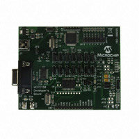
MCP2150DM
Description
BOARD DEMO FOR MCP2150
Manufacturer
Microchip Technology
Specifications of MCP2150DM
Main Purpose
Interface, IrDA
Embedded
Yes, MCU, 8-Bit
Utilized Ic / Part
MCP2150
Primary Attributes
IrDA Controller with PIC18F MCU
Secondary Attributes
USB Interface
Processor To Be Evaluated
MCP2150, MCP2155
Processor Series
MCP215x
Interface Type
USB
Lead Free Status / RoHS Status
Lead free / RoHS Compliant
Lead Free Status / RoHS Status
Lead free / RoHS Compliant, Lead free / RoHS Compliant


2.11
An IR link can be compared to a one-wire data connec-
tion. The IR transceiver can transmit or receive, but not
both at the same time. A delay of one bit time is recom-
mended between the time a byte is received and
another byte is transmitted.
2.12
The baud rate for the MCP2150 IR port (the TXIR and
RXIR pins) is, initially, at the default rate of 9600 baud.
The Primary device determines the maximum baud
rate that the MCP2150 will operate at. This information
is used during NDM, with the Primary device setting the
baud rate of the IR link. The maximum IR baud rate is
not required to be the same as the MCP2150’s serial
port (UART) baud rate (as determined by the
BAUD1:BAUD0 pins).
2.13
The MCP2150 has a flexible feature that allows the
MCP2150 Device ID to be changed by the Host Con-
troller. The default ID is “Generic IrDA” and is stored in
non-volatile, electrically erasable programmable mem-
ory (EEPROM). The maximum ID String length is 19
bytes. The format of the ID EEPROM is shown in
Figure 2-11.
The ID String must only contain the ASCII characters
from 20h to 7Ah (inclusive).
The MCP2150 enters into ID String programming when
it exits the reset state and detects that the DTR pin is
high and the RTS pin is low.
A Host Controller connected to the MCP2150 would,
typically, perform the following steps to place the
MCP2150 into ID String programming mode:
1.
2.
3.
4.
FIGURE 2-11:
2002 Microchip Technology Inc.
Force the MCP2150 into reset (RESET pin
forced low).
Force the DTR pin high and the RTS pin low.
Release the MCP2150 from reset (RESET pin
forced high).
Wait for device to complete initialization.
Turnaround Latency
IR Port Baud Rate
Programmable Device ID
ID STRING FORMAT
1st Byte
Transferred
Length
1 Byte
ID String
1 to 19 Bytes
Preliminary
TABLE 2-5:
Once the MCP2150 is ready to receive data, the CTS
pin will be forced low. Data may now be transferred, fol-
lowing the format in Figure 2-11. The CTS pin deter-
mines the flow control and the Host Controller must
monitor this signal to ensure that the data byte may be
sent.
Once the Host Controller has sent its last byte, the DTR
pin must be set low. This ensures that, if another reset
occurs, the MCP2150 will not reenter ID String pro-
gramming mode. The MCP2150 uses the String Length
(1st byte transmitted) to determine when the ID String
programming mode has completed. This returns the
MCP2150 to normal operation.
Example 2-1
PIC16CXXX acting as the Host Controller to modify the
MCP2150 Device ID String.
* Until device initialization is complete.
DTR
Note 1: If a non-valid ID String (containing an ASCII
0
1
1
2: The communication program supplied with
character not in the valid range) is
programmed, the MCP2150 will not create
a link with a Primary device.
Microsoft’s Windows
(called HyperTerminal) may leave the DTR
signal high and the RTS signals low when
the program disconnects, or is closed. Care
should be taken to ensure that this does not
accidently cause the MCP2150 to enter
Device ID String Programming.
RTS
Last Byte
Transferred
X
0
1
shows
DTR/RTS STATE & DEVICE
MODE
After Device Reset *
Enter Normal Mode
Enter Programmable Device ID
Enter Normal Mode
the
firmware
MCP2150
®
DS21655B-page 19
operating system
code
for
a
Related parts for MCP2150DM
Image
Part Number
Description
Manufacturer
Datasheet
Request
R

Part Number:
Description:
Manufacturer:
Microchip Technology Inc.
Datasheet:
Part Number:
Description:
Manufacturer:
Microchip Technology Inc.
Datasheet:
Part Number:
Description:
Manufacturer:
Microchip Technology Inc.
Datasheet:
Part Number:
Description:
Manufacturer:
Microchip Technology Inc.
Datasheet:
Part Number:
Description:
Manufacturer:
Microchip Technology Inc.
Datasheet:
Part Number:
Description:
Manufacturer:
Microchip Technology Inc.
Datasheet:
Part Number:
Description:
Manufacturer:
Microchip Technology Inc.
Datasheet:
Part Number:
Description:
Manufacturer:
Microchip Technology Inc.
Datasheet: