MCP73871EV Microchip Technology, MCP73871EV Datasheet - Page 27
MCP73871EV
Manufacturer Part Number
MCP73871EV
Description
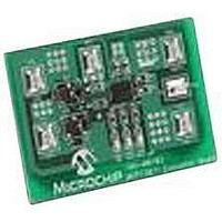
EVALUATION BOARD FOR MCP73871
Manufacturer
Microchip Technology
Type
Battery Managementr
Specifications of MCP73871EV
Main Purpose
Power Management, Battery Charger
Embedded
No
Utilized Ic / Part
MCP73871
Primary Attributes
1 Cell- Li-Ion / Li-Pol, 4.2V @ 100 or 500mA: USB, 1.65A: AC Adaptor
Secondary Attributes
LED Status Indicators
Silicon Manufacturer
Microchip
Application Sub Type
Battery Charger
Kit Application Type
Power Management - Battery
Silicon Core Number
MCP73871
Product
Power Management Modules
Kit Contents
Board
Lead Free Status / RoHS Status
Lead free / RoHS Compliant
For Use With/related Products
MCP73871
Lead Free Status / RoHS Status
Lead free / RoHS Compliant


For example, by utilizing a 10 kΩ at 25°C NTC
thermistor with a sensitivity index, β, of 3892, the
charge temperature range can be set to 0°C - 50°C by
placing a 1.54 kΩ resistor in series (R
69.8 kΩ resistor in parallel (R
6.1.1.6
A status output provides information on the state of
charge. The output can be used to illuminate external
LEDs or interface to a host microcontroller. Refer to
Table 5-1
output during a charge cycle.
6.1.1.7
The preferred discharge current for Lithium-Ion cells
should always follow references and guidance from
battery manufacturers. Due to the safety concerns
when
dissipation of linear solutions, the system load when
design with the MCP73871 device is recommended to
be less than 1A or the maximum discharge rate of the
selected Lithium-Ion cell. Whichever is smaller is
recommended.
The idea diode between V
drive a maximum current up to 2A. The built-in thermal
shutdown protection may turn the MCP73871 device
off with high current.
© 2009 Microchip Technology Inc.
using
for a summary of the state of the status
Charge Status Interface
System Load Current
Lithium-Ion
BAT
T2
batteries
and OUT is designed to
) with the thermistor.
and
T1
), and a
power
6.2
For optimum voltage regulation, place the battery pack
as close as possible to the device’s V
recommended to minimize voltage drops along the
high current-carrying PCB traces.
If the PCB layout is used as a heatsink, adding many
vias in the heatsink pad can help conduct more heat to
the backplane of the PCB, thus reducing the maximum
junction temperature.
PCB Layout Issues
MCP73871
DS22090B-page 27
BAT
and V
SS
pins,
Related parts for MCP73871EV
Image
Part Number
Description
Manufacturer
Datasheet
Request
R

Part Number:
Description:
Manufacturer:
Microchip Technology Inc.
Datasheet:
Part Number:
Description:
Manufacturer:
Microchip Technology Inc.
Datasheet:
Part Number:
Description:
Manufacturer:
Microchip Technology Inc.
Datasheet:
Part Number:
Description:
Manufacturer:
Microchip Technology Inc.
Datasheet:
Part Number:
Description:
Manufacturer:
Microchip Technology Inc.
Datasheet:
Part Number:
Description:
Manufacturer:
Microchip Technology Inc.
Datasheet:
Part Number:
Description:
Manufacturer:
Microchip Technology Inc.
Datasheet:
Part Number:
Description:
Manufacturer:
Microchip Technology Inc.
Datasheet: