MCP73871EV Microchip Technology, MCP73871EV Datasheet - Page 17
MCP73871EV
Manufacturer Part Number
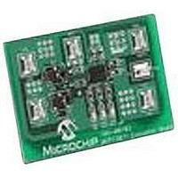
MCP73871EV
Description
EVALUATION BOARD FOR MCP73871
Manufacturer
Microchip Technology
Type
Battery Managementr
Specifications of MCP73871EV
Main Purpose
Power Management, Battery Charger
Embedded
No
Utilized Ic / Part
MCP73871
Primary Attributes
1 Cell- Li-Ion / Li-Pol, 4.2V @ 100 or 500mA: USB, 1.65A: AC Adaptor
Secondary Attributes
LED Status Indicators
Silicon Manufacturer
Microchip
Application Sub Type
Battery Charger
Kit Application Type
Power Management - Battery
Silicon Core Number
MCP73871
Product
Power Management Modules
Kit Contents
Board
Lead Free Status / RoHS Status
Lead free / RoHS Compliant
For Use With/related Products
MCP73871
Lead Free Status / RoHS Status
Lead free / RoHS Compliant


3.14
The timer enable (TE) feature is used to enable or
disable the internal timer. A low signal on this pin
enables the internal timer and a high signal disables
the internal timer. The TE input can be used to disable
the timer when the system load is substantially limiting
the available supply current to charge the battery. The
TE input is compatible with 1.8V logic.
3.15
The MCP73871 device continuously monitor battery
temperature during a charge cycle by measuring the
voltage between the THERM and V
50 µA current source provides the bias for most
common
thermistors (NTC). The MCP73871 device compares
the voltage at the THERM pin to factory set thresholds
of 1.24V and 0.25V, typically. Once a voltage outside
the thresholds is detected during a charge cycle, the
MCP73871 device immediately suspends the charge
cycle. The charge cycle resumes when the voltage at
the THERM pin returns to the normal range. The
charge temperature window can be set by placing fixed
value resistors in series-parallel with a thermistor.
Refer to Section 6.0 “Applications” for calculations
of resistance values.
© 2009 Microchip Technology Inc.
Note:
Timer Enable (TE)
Battery Temperature Monitor
(THERM)
10 kΩ
The built-in safety timer is available for the
following options: 4 HR, 6 HR and 8 HR.
negative-temperature
SS
pins. An internal
coefficient
3.16
With the CE input Low, the Li-Ion battery charger
feature of the MCP73871 will be disabled. The charger
feature is enabled when CE is active High. Allowing the
CE pin to float during the charge cycle may cause
system instability. The CE input is compatible with 1.8V
logic. Refer to Section 6.0 “Applications” for various
applications in designing with CE features.
3.17
There is an internal electrical connection between the
Exposed Thermal Pad (EP) and the V
be connected to the same potential.
Charge Enable (CE)
Exposed Thermal Pad (EP)
MCP73871
DS22090B-page 17
SS
pin; they must
Related parts for MCP73871EV
Image
Part Number
Description
Manufacturer
Datasheet
Request
R

Part Number:
Description:
Manufacturer:
Microchip Technology Inc.
Datasheet:
Part Number:
Description:
Manufacturer:
Microchip Technology Inc.
Datasheet:
Part Number:
Description:
Manufacturer:
Microchip Technology Inc.
Datasheet:
Part Number:
Description:
Manufacturer:
Microchip Technology Inc.
Datasheet:
Part Number:
Description:
Manufacturer:
Microchip Technology Inc.
Datasheet:
Part Number:
Description:
Manufacturer:
Microchip Technology Inc.
Datasheet:
Part Number:
Description:
Manufacturer:
Microchip Technology Inc.
Datasheet:
Part Number:
Description:
Manufacturer:
Microchip Technology Inc.
Datasheet: