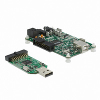
USB AUDIO 2.0 REFERENCE DESIGN XMOS, USB AUDIO 2.0 REFERENCE DESIGN Datasheet - Page 30

USB AUDIO 2.0 REFERENCE DESIGN
Manufacturer Part Number
USB AUDIO 2.0 REFERENCE DESIGN
Description
USB AUDIO 2.0 REFERENCE DESIGN
Manufacturer
XMOS
Datasheets
1.USB_AUDIO_2.0_REFERENCE_DESIGN.pdf
(18 pages)
2.USB_AUDIO_2.0_REFERENCE_DESIGN.pdf
(6 pages)
3.USB_AUDIO_2.0_REFERENCE_DESIGN.pdf
(2 pages)
4.USB_AUDIO_2.0_REFERENCE_DESIGN.pdf
(57 pages)
Specifications of USB AUDIO 2.0 REFERENCE DESIGN
Design Resources
USB AUDIO Schematic
Main Purpose
Audio, Audio Processing
Embedded
Yes
Utilized Ic / Part
XS1-L1
Primary Attributes
Audio data up to 24-bit @ 192kHz
Secondary Attributes
I²S and S/PDIF
Lead Free Status / RoHS Status
Lead free / RoHS Compliant
Other names
880-1017
The channel status bits are 0x0nc07A4, where c=1 for left channel, c=2 for right
XS1 devices can support S/PDIF receive up to 192kHz.
The S/PDIF receiver module uses a clockblock and a buffered one-bit port. The
4-bits.
The receiver outputs audio samples over a streaming channel end where data can be
The S/PDIF receive function never returns. The 32-bit value from the channel input
The tag has one of three values:
USB Audio Software Design Guide
channel and n indicates sampling frequency:
3.9 S/PDIF Receive
clock-block is divided of a 100 MHz reference clock. The one bit port is buffered to
input using the built-in input operator.
comprises:
Frequency (kHz)
n
0:3
4:28
29:31
FRAME_X
FRAME_Y
FRAME_Z
Bits
Tag
A tag (see below)
PCM encoded sample value
User bits (parity, etc)
Sample on channel 0 (Left for stereo)
Sample on another channel (Right if for stereo)
Sample on channel 0 (Left), and the first sample of a frame;
can be used if the user bits need to be reconstructed.
44.1
0
Meaning
Table 16: S/PDIF RX Word Structure
Table 15: Channel Status Bits
Table 17: S/PDIF RX Tags
48
2
88.2
8
96
A
Document Revision 1.2
176.4
C
192
E
30/57


