SI5338-EVB Silicon Laboratories Inc, SI5338-EVB Datasheet - Page 29
SI5338-EVB
Manufacturer Part Number
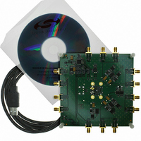
SI5338-EVB
Description
BOARD EVALUATION SI5338
Manufacturer
Silicon Laboratories Inc
Datasheet
1.SI5338B-A-GM.pdf
(42 pages)
Specifications of SI5338-EVB
Main Purpose
Timing, Clock Generator
Embedded
No
Utilized Ic / Part
Si5338
Primary Attributes
160 kHz to 700 MHz in LVPECL/LVDS,
Secondary Attributes
USB Based GUI to Program, I2C/SMBus Compatible Interface, 1.8, 2.5, or 3.3 V
For Use With/related Products
Si5330/34/38 Family
Lead Free Status / RoHS Status
Lead free / RoHS Compliant
Lead Free Status / RoHS Status
Lead free / RoHS Compliant, Lead free / RoHS Compliant
Other names
336-1556


5. I
Configuration and operation of the Si5338 is controlled
by reading and writing to the RAM space using the I
interface. The device operates in slave mode with 7-bit
addressing
(100 kbps) or Fast-Mode (400 kbps) and supports burst
data transfer with auto address increments.
The I
(SDA) and a serial clock input (SCL) as shown in
Figure 21. Both the SDA and SCL pins must be
connected to the VDD supply via an external pull-up as
recommended by the I
The 7-bit device (slave) address of the Si5338 consists
of a 6-bit fixed address plus a user-selectable LSB bit as
shown in Figure 22. The LSB bit is selectable using the
optional I2C_LSB pin which is available as an ordering
option for applications that require more than one
Si5338 on a single I
I2C_LSB pin option have a fixed 7-bit address of 70h
(111 0000) as shown in Figure 22. Other custom I
addresses are also possible. See Table 16 for details on
device ordering information with the optional I2C_LSB
pin.
Data is transferred MSB first in 8-bit words as specified
by the I
7-bit device (slave) address + a write bit, an 8-bit
register address, and 8 bits of data as shown in
Figure 23. A write burst operation is also shown where
every additional data word is written using an auto-
incremented address.
I
2
C Bus
(without I2C_LSB Option)
(with I2C_LSB Option)
Slave Address
Slave Address
2
2
C bus consists of a bidirectional serial data line
C Interface
Figure 22. Si5338 I
2
Figure 21. I
C specification. A write command consists of a
V
and
DD
0/1
can
1 1 1 0 0 0 0/1
6
1 1 1 0 0 0
6
2
C and Control Signals
5
5
2
I2C_LSB
C specification.
2
4
4
C bus. Devices without the
SDA
SCL
operate
3
3
2
2
2
C Slave Address
1
1
I2C_LSB/PDEC/FDEC
0
0
0
in
OEB/PINC/FINC
I2C_LSB pin
Standard-Mode
Control
2
2
Rev. 1.0
C
C
A read operation is performed in two stages. A data
write is used to set the register address, then a data
read is performed to retrieve the data from the set
address. A read burst operation is also supported. This
is shown in Figure 24.
AC and dc electrical specifications for the SCL and SDA
pins are shown in Table 14. The timing specifications
and timing diagram for the I
the I
compatibility with SMBus interfaces.
The I
3.63 V and is 3.3 V tolerant. If a bus voltage of less than
2.5 V is used, register 27[7] = 1 must be written to
maintain compatibility with the I
Write Operation – Single Byte
Read Operation – Single Byte
Read Operation - Burst (Auto Address Increment)
Write Operation - Burst (Auto Address Increment)
S
S
S
S
S
S
2
2
Slv Addr [6:0]
Slv Addr [6:0]
Slv Addr [6:0]
Slv Addr [6:0]
Slv Addr [6:0]
Slv Addr [6:0]
C-Bus Standard. SDA timeout is supported for
C bus can be operated at a bus voltage of 1.71 to
From slave to master
From master to slave
From slave to master
From master to slave
Figure 23. I
Figure 24. I
1 A
0 A Reg Addr [7:0]
1 A
0 A Reg Addr [7:0]
0 A Reg Addr [7:0]
0 A Reg Addr [7:0]
Data [7:0]
Data [7:0] A
2
2
C Write Operation
C Read Operation
1 – Read
0 – Write
A – Acknowledge (SDA LOW)
N – Not Acknowledge (SDA HIGH)
S – START condition
P – STOP condition
1 – Read
0 – Write
A – Acknowledge (SDA LOW)
N – Not Acknowledge (SDA HIGH)
S – START condition
P – STOP condition
N
2
C bus are compatible with
A P
A Data [7:0]
A Data [7:0] A Data [7:0]
A P
P
Data [7:0]
Reg Addr +1
2
C bus standard.
N
A
P
Si5338
Reg Addr +1
P
A
P
29
Related parts for SI5338-EVB
Image
Part Number
Description
Manufacturer
Datasheet
Request
R

Part Number:
Description:
KIT PROG FIELD SI5338/4/0
Manufacturer:
Silicon Laboratories Inc
Datasheet:

Part Number:
Description:
Programmers & Debuggers Si5338/4/0 field programming kit
Manufacturer:
Silicon Laboratories Inc
Datasheet:
Part Number:
Description:
SMD/C°/SINGLE-ENDED OUTPUT SILICON OSCILLATOR
Manufacturer:
Silicon Laboratories Inc
Part Number:
Description:
Manufacturer:
Silicon Laboratories Inc
Datasheet:
Part Number:
Description:
N/A N/A/SI4010 AES KEYFOB DEMO WITH LCD RX
Manufacturer:
Silicon Laboratories Inc
Datasheet:
Part Number:
Description:
N/A N/A/SI4010 SIMPLIFIED KEY FOB DEMO WITH LED RX
Manufacturer:
Silicon Laboratories Inc
Datasheet:
Part Number:
Description:
N/A/-40 TO 85 OC/EZLINK MODULE; F930/4432 HIGH BAND (REV E/B1)
Manufacturer:
Silicon Laboratories Inc
Part Number:
Description:
EZLink Module; F930/4432 Low Band (rev e/B1)
Manufacturer:
Silicon Laboratories Inc
Part Number:
Description:
I°/4460 10 DBM RADIO TEST CARD 434 MHZ
Manufacturer:
Silicon Laboratories Inc
Part Number:
Description:
I°/4461 14 DBM RADIO TEST CARD 868 MHZ
Manufacturer:
Silicon Laboratories Inc
Part Number:
Description:
I°/4463 20 DBM RFSWITCH RADIO TEST CARD 460 MHZ
Manufacturer:
Silicon Laboratories Inc
Part Number:
Description:
I°/4463 20 DBM RADIO TEST CARD 868 MHZ
Manufacturer:
Silicon Laboratories Inc
Part Number:
Description:
I°/4463 27 DBM RADIO TEST CARD 868 MHZ
Manufacturer:
Silicon Laboratories Inc
Part Number:
Description:
I°/4463 SKYWORKS 30 DBM RADIO TEST CARD 915 MHZ
Manufacturer:
Silicon Laboratories Inc