TEMPCOMPRTC-RD Silicon Laboratories Inc, TEMPCOMPRTC-RD Datasheet - Page 7
TEMPCOMPRTC-RD
Manufacturer Part Number
TEMPCOMPRTC-RD
Description
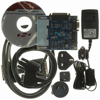
KIT REF DES TEMP COMPENS RTC
Manufacturer
Silicon Laboratories Inc
Datasheet
1.TEMPCOMPRTC-RD.pdf
(14 pages)
Specifications of TEMPCOMPRTC-RD
Main Purpose
Timing, Real Time Clock (RTC)
Embedded
Yes, MCU, 8-Bit
Utilized Ic / Part
C8051F300
Primary Attributes
I²C, RS-232, SMBus Interfaces
Secondary Attributes
A Keil Compiler and USB Debug Adapter are required
Processor To Be Evaluated
C8051F300
Interface Type
RS-232
Lead Free Status / RoHS Status
Contains lead / RoHS non-compliant
Lead Free Status / RoHS Status
Lead free / RoHS Compliant, Contains lead / RoHS non-compliant
Other names
336-1351


3. Before connecting to the target device, several connection options may need to be set. Open the “Connection
4. Click the “Connect” button in the toolbar or select “Debug→Connect” from the menu to connect to the device.
5. Choose the “Project→Download Object File…” option. This shows a “Download” dialog. Click the ”Browse”
6. Click the “Download” button to download this firmware to the ‘F300 device. You will see the text “Download
7. Disconnect the dc power adapter and the ribbon cable from the target board.
6.2.2. Hardware Setup
1. Connect the DB25 parallel cable provided with the kit between the PC’s parallel port (printer port) and the 25-pin
2. Apply power to the board by connecting the dc power adapter.
Options” window by selecting “Options→Connection Options...” in the IDE menu. First, select the adapter that
you are using in the “Serial Adapter” section. Next, the correct “Debug Interface” must be selected. C8051F30x
family devices use the Silicon Labs 2-wire (C2) debug interface. Once these selections are made, click the OK
button to close the window.
You will see the text “Target: C8051F300” in the status bar of the IDE if the connection was successful.
button and select the TC-RTC firmware pre-linked OMF file from this path:
C:\Silabs\MCU\TemperatureCompensated_RTC_RD\Firmware\TEMPCOMPRTC_RD_SMBUS.OMF
successful” in the Build window if the firmware was downloaded successfully.
connector on the TC-RTC Evaluation board (J6).
Figure 7. Hardware Setup using a USB Debug Adapter
Figure 6. Hardware Setup using a Serial Adapter
Rev. 0.1
TEMPCOMPRTC-RD
7
Related parts for TEMPCOMPRTC-RD
Image
Part Number
Description
Manufacturer
Datasheet
Request
R

Part Number:
Description:
SMD/C°/SINGLE-ENDED OUTPUT SILICON OSCILLATOR
Manufacturer:
Silicon Laboratories Inc
Part Number:
Description:
Manufacturer:
Silicon Laboratories Inc
Datasheet:
Part Number:
Description:
N/A N/A/SI4010 AES KEYFOB DEMO WITH LCD RX
Manufacturer:
Silicon Laboratories Inc
Datasheet:
Part Number:
Description:
N/A N/A/SI4010 SIMPLIFIED KEY FOB DEMO WITH LED RX
Manufacturer:
Silicon Laboratories Inc
Datasheet:
Part Number:
Description:
N/A/-40 TO 85 OC/EZLINK MODULE; F930/4432 HIGH BAND (REV E/B1)
Manufacturer:
Silicon Laboratories Inc
Part Number:
Description:
EZLink Module; F930/4432 Low Band (rev e/B1)
Manufacturer:
Silicon Laboratories Inc
Part Number:
Description:
I°/4460 10 DBM RADIO TEST CARD 434 MHZ
Manufacturer:
Silicon Laboratories Inc
Part Number:
Description:
I°/4461 14 DBM RADIO TEST CARD 868 MHZ
Manufacturer:
Silicon Laboratories Inc
Part Number:
Description:
I°/4463 20 DBM RFSWITCH RADIO TEST CARD 460 MHZ
Manufacturer:
Silicon Laboratories Inc
Part Number:
Description:
I°/4463 20 DBM RADIO TEST CARD 868 MHZ
Manufacturer:
Silicon Laboratories Inc
Part Number:
Description:
I°/4463 27 DBM RADIO TEST CARD 868 MHZ
Manufacturer:
Silicon Laboratories Inc
Part Number:
Description:
I°/4463 SKYWORKS 30 DBM RADIO TEST CARD 915 MHZ
Manufacturer:
Silicon Laboratories Inc
Part Number:
Description:
N/A N/A/-40 TO 85 OC/4463 RFMD 30 DBM RADIO TEST CARD 915 MHZ
Manufacturer:
Silicon Laboratories Inc
Part Number:
Description:
I°/4463 20 DBM RADIO TEST CARD 169 MHZ
Manufacturer:
Silicon Laboratories Inc