TEMPCOMPRTC-RD Silicon Laboratories Inc, TEMPCOMPRTC-RD Datasheet
TEMPCOMPRTC-RD
Specifications of TEMPCOMPRTC-RD


Related parts for TEMPCOMPRTC-RD

TEMPCOMPRTC-RD Summary of contents
Page 1
... Silicon Labs IDE. For a list of currently sup- ported tool chains, please refer to the following MCU Knowledge Base Article: cle.asp?article=173563&p=4120 Rev. 0.1 5/06 TEMPCOMPRTC- Copyright © 2006 by Silicon Laboratories interface) http://portal.knowledgebase.net/arti- TEMPCOMPRTC-RD ...
Page 2
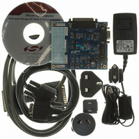
... TEMPCOMPRTC-RD 3. Kit Overview The Temperature Compensated Real Time Clock (TC-RTC) Reference Design Kit includes an evaluation board that utilizes a Silicon Laboratories C8051F300 Mixed Signal Microcontroller. This kit offers the following features: Low-cost Temperature Compensated Real Time Clock and Calendar 56-byte General Purpose Non-Volatile RAM ...
Page 3
... SMBus interface via a DB25 connector. The preloaded firmware is built to work with the RS-232 serial interface. Also included in the AN293SW.zip package is a pre-built OMF file, which enables the SMBus interface to the RTC when loaded into the device. The AN293SW.zip package contains the full source code as well. TEMPCOMPRTC-RD Rev. 0.1 3 ...
Page 4
... TEMPCOMPRTC-RD 6. TC-RTC Demonstration The following step-by-step demonstration explains the various features and capabilities of this reference design. There are two interfaces available for the RTC—UART and SMBus, which are demonstrated in sections 6.1 and 6.2, respectively. 6.1. UART Interface Demonstration The TC-RTC Evaluation Board comes preloaded with firmware that enables the UART interface. The following sections show how to set up and use this interface ...
Page 5
... RTC: Supported Commands" on page 11 for command formats. w000709316604040506 5. Type the “r” command (read) to get the current time and date information from the device. r0007 6. Type the “s” command to toggle on the auto-display mode. TEMPCOMPRTC-RD Figure 4. HyperTerminal ASCII Setup Rev. 0.1 5 ...
Page 6
... TEMPCOMPRTC-RD Figure 5. Interacting with the TC-RTC—HyperTerminal Session An index of all supported commands is available in "Appendix A—TC-RTC: Supported Commands" on page 11. Detailed information about this reference design is contained in “AN293: Temperature Compensated Real Time Clock Reference Design Programmer’s Guide”. 6.2. SMBus Interface Demonstration The TC-RTC Evaluation Board can be loaded with firmware that can enable an SMBus/I described in the following sections ...
Page 7
... Disconnect the dc power adapter and the ribbon cable from the target board. 6.2.2. Hardware Setup 1. Connect the DB25 parallel cable provided with the kit between the PC’s parallel port (printer port) and the 25-pin connector on the TC-RTC Evaluation board (J6). 2. Apply power to the board by connecting the dc power adapter. TEMPCOMPRTC-RD Rev. 0.1 7 ...
Page 8
... TEMPCOMPRTC-RD 6.2.3. Interacting with the Windows SMBus Test Software The TC-RTC Evaluation Board with the SMBus firmware enables an SMBus/I test this interface, PC software is provided that emulates an SMBus master via the PC’s parallel port. 1. The PC Software is installed as part of the TC-RTC RD installation from the Reference Design Kit CD. Launch this by selecting the following: Start Menu→ ...
Page 9
... Schematic GND4 7 GND3 6 GND2 3 GND1 2 TEMPCOMPRTC- Rev. 0.1 9 ...
Page 10
... TEMPCOMPRTC-RD 8. Bill of Materials Item Qty Reference 1 13 C1,C2,C4,C6,C10 C12,C13,C14,C15 C16,C17,C18,C19 2 2 C11,C20 1000uF/16V C8, HEADER 6X2 HEADER4X2 DB9 Female DB25Female PHONEJACK 17 2 R2,R23 18 2 R4, R10,R14,R15 21 1 R16 22 6 R8,R9,R11,R12,R 21,R22 23 1 R13 24 1 R17 25 1 R18 26 2 R19,R20 27 2 SW1,SW2 PUSHBUTTON 28 6 TP31,TP33,TP36, ...
Page 11
... Mode, it receives address and data from the Master and writes it to the RTC or NVRAM registers. In Slave Transmitter Mode, it sends data from the RTC or NVRAM registers to the Master. Refer to "AN293: Temperature Compensated Real Time Clock Reference Design Programmer's Guide" for more details on the SMBus interface implementation. TEMPCOMPRTC-RD C UPPORTED OMMANDS Rev ...
Page 12
... TEMPCOMPRTC-RD A B—TC-RTC: I PPENDIX UART Communication Parameters Baud rate: 9600 bps Data format: 8 data bits, 1 stop bit, no parity Flow control: None RTC and NVRAM Registers—Data Format Bit7 Address 00H CH 01H 0 02H 0 03H 0 04H 0 05H 0 06H 07H 08H 3FH Figure 10. ...
Page 13
... N : OTES TEMPCOMPRTC-RD Rev. 0.1 13 ...
Page 14
... TEMPCOMPRTC-RD Contact Information Silicon Laboratories Inc. 4635 Boston Lane Austin, TX 78735 Email: MCUinfo@silabs.com Internet: www.silabs.com The information in this document is believed to be accurate in all respects at the time of publication but is subject to change without notice. Silicon Laboratories assumes no responsibility for errors and omissions, and disclaims responsibility for any consequences resulting from the use of information included herein ...