SPUSI2/NOPB National Semiconductor, SPUSI2/NOPB Datasheet - Page 6
SPUSI2/NOPB
Manufacturer Part Number
SPUSI2/NOPB
Description
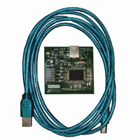
BOARD EVAL DATA CAPTURE BOARD
Manufacturer
National Semiconductor
Specifications of SPUSI2/NOPB
Main Purpose
Interface, Data Capture
Embedded
Yes, MCU, 8-Bit
Utilized Ic / Part
WEBENCH® Sensor Designer Boards
Primary Attributes
USB Interface Dongle II
Secondary Attributes
SPI Interface
Lead Free Status / RoHS Status
Lead free / RoHS Compliant
Other names
SPUSI2
Available stocks
Company
Part Number
Manufacturer
Quantity
Price
Company:

Part Number:
SPUSI2/NOPB
Manufacturer:
National Semiconductor
Quantity:
135


calibration correspond to the selected channel. The term current channel is also
used in this document to refer to this selected channel.
3.1.2 Channel Enable.
displaying the channel sensor measurements. The initial enable or disable state
is determined by the board configuration. A channel may be enabled or disabled
at any time by clicking on the color channel state indicator in its respective pane.
3.2 Channel Properties.
measurement display. These properties are defined in more detail in the board
specific documentation.
3.2.1
the suitable units such as mV/C. When the sensitivity value is not applicable, it is
not displayed on the Control Panel.
device properties and not allow the user to make changes to the value.
All channel specific actions such as Configuration Panel settings and
Any present channel pane may be enabled or disabled for gathering and
Each channel has various properties that must be defined for proper
Sensitivity
The sensitivity value is entered in the corresponding window, along with
Some applications may use a fixed sensitivity value or predetermined
Figure 3-6: Sensitivity Window disabled with device name
.
Figure 3-5: Disabled Channel with Grey Indicator.
Figure 3-5: Sensitivity Window with Units.
Figure 3-4: Selected Channel.
Related parts for SPUSI2/NOPB
Image
Part Number
Description
Manufacturer
Datasheet
Request
R

Part Number:
Description:
National Semiconductor [8-Bit D/A Converter]
Manufacturer:
National Semiconductor
Datasheet:
Part Number:
Description:
National Semiconductor [Media Coprocessor]
Manufacturer:
National Semiconductor
Datasheet:
Part Number:
Description:
Digitally Controlled Tone and Volume Circuit with Stereo Audio Power Amplifier, Microphone Preamp Stage and National 3D Sound
Manufacturer:
National Semiconductor
Datasheet:
Part Number:
Description:
Digitally Controlled Tone and Volume Circuit with Stereo Audio Power Amplifier, Microphone Preamp Stage and National 3D Sound
Manufacturer:
National Semiconductor
Datasheet:
Part Number:
Description:
AC97 Rev 2 Codec with Sample Rate Conversion and National 3D Sound
Manufacturer:
National Semiconductor
Part Number:
Description:
Manufacturer:
National Semiconductor
Datasheet:
Part Number:
Description:
Manufacturer:
National Semiconductor
Datasheet:
Part Number:
Description:
General Purpose, Low Voltage, Low Power, Rail-to-Rail Output Operational Amplifiers
Manufacturer:
National Semiconductor
Datasheet:
Part Number:
Description:
8-bit 20 MSPS flash A/D converter.
Manufacturer:
National Semiconductor
Datasheet:
Part Number:
Description:
Low Noise Quad Operational Amplifier
Manufacturer:
National Semiconductor
Datasheet:
Part Number:
Description:
Quad Differential Line Receivers
Manufacturer:
National Semiconductor
Datasheet:
Part Number:
Description:
Quad High Speed Trapezoidal? Bus Transceiver
Manufacturer:
National Semiconductor
Datasheet:
Part Number:
Description:
Dual Line Receiver
Manufacturer:
National Semiconductor
Datasheet:
Part Number:
Description:
TTL to 10k ECL Level Translator with Latch
Manufacturer:
National Semiconductor
Datasheet: