DEMO9S08MP16 Freescale Semiconductor, DEMO9S08MP16 Datasheet - Page 20
DEMO9S08MP16
Manufacturer Part Number
DEMO9S08MP16
Description
BOARD DEMO FOR MC9S08MP16
Manufacturer
Freescale Semiconductor
Specifications of DEMO9S08MP16
Main Purpose
Power Management, Motor Control
Embedded
*
Utilized Ic / Part
MC9S08MP16
Primary Attributes
*
Secondary Attributes
*
Processor To Be Evaluated
MC9S08MP16
Interface Type
RS232, USB
Operating Supply Voltage
6 V
Silicon Manufacturer
Freescale
Core Architecture
HCS08
Core Sub-architecture
HCS08
Silicon Core Number
MC9S08
Silicon Family Name
S08MP
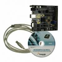
Kit Contents
Demo Board USB Cable DVD
Rohs Compliant
Yes
Tool Type
Demonstration Board
Cpu Core
HCS08
Data Bus Width
8 bit
Lead Free Status / RoHS Status
Lead free / RoHS Compliant


6.4
16
Serial Grapher Application
In order to unsecure a device with this application, please specify the
hardware interface that you are using. If your P&E Multilink or Cyclone PRO is
successfully detected, the name of a corresponding device will appear in the
Port text box. Please select HCS08 or CFV1 from the Select Architecture drop
down menu and press the Perform Unsecure button. The application will
finish unsecuring and erasing the device shortly thereafter.
This PC-based application is included on the DVD-ROM that accompanies
the DEMO9S08MP16, and may also be found at:
http://www.pemicro.com/fixedlinks/demotoolkit.cfm.
This PC-based application is a serial graphing utility that may be used with
microcontroller code which transmits data in the correct format. It allows
incoming data on the PC serial port (or one of P&E’s virtual serial ports) to be
automatically graphed in time or displayed as a series of bar graphs. The
virtual serial port exists on several of P&E’s Embedded Multilink designs
including the DEMO9S08MP16 board.
To start using this application, please choose COM or virtual USB COM
settings from the drop-down Port menu. By doing so, you are specifying the
port on the evaluation board that will be used for transmitting captured
accelerometer data via a COM or USB serial port. Please make sure that
jumpers J4 and J5 are set accordingly. Prior to starting serial data capture,
please specify the Baud setting to reflect the parameter at which your serial
communication interface is operating. Once your port settings are configured,
please plug a USB or DB9 serial cable into the evaluation board and click on
the Open Serial Port and Start Demo buttons. The graphing of data can be
Figure 6-3: Unsecure Application
DEMO9S08MP16 User Manual
Related parts for DEMO9S08MP16
Image
Part Number
Description
Manufacturer
Datasheet
Request
R

Part Number:
Description:
Manufacturer:
Freescale Semiconductor, Inc
Datasheet:
Part Number:
Description:
Manufacturer:
Freescale Semiconductor, Inc
Datasheet:
Part Number:
Description:
Manufacturer:
Freescale Semiconductor, Inc
Datasheet:
Part Number:
Description:
Manufacturer:
Freescale Semiconductor, Inc
Datasheet:
Part Number:
Description:
Manufacturer:
Freescale Semiconductor, Inc
Datasheet:
Part Number:
Description:
Manufacturer:
Freescale Semiconductor, Inc
Datasheet:
Part Number:
Description:
Manufacturer:
Freescale Semiconductor, Inc
Datasheet:
Part Number:
Description:
Manufacturer:
Freescale Semiconductor, Inc
Datasheet:
Part Number:
Description:
Manufacturer:
Freescale Semiconductor, Inc
Datasheet:
Part Number:
Description:
Manufacturer:
Freescale Semiconductor, Inc
Datasheet:
Part Number:
Description:
Manufacturer:
Freescale Semiconductor, Inc
Datasheet:
Part Number:
Description:
Manufacturer:
Freescale Semiconductor, Inc
Datasheet:
Part Number:
Description:
Manufacturer:
Freescale Semiconductor, Inc
Datasheet:
Part Number:
Description:
Manufacturer:
Freescale Semiconductor, Inc
Datasheet:
Part Number:
Description:
Manufacturer:
Freescale Semiconductor, Inc
Datasheet: