ISD-ES15100_USB Nuvoton Technology Corporation of America, ISD-ES15100_USB Datasheet - Page 21
ISD-ES15100_USB
Manufacturer Part Number
ISD-ES15100_USB
Description
BOARD EVALUATION USB FOR I15100
Manufacturer
Nuvoton Technology Corporation of America
Series
ChipCorder®r
Specifications of ISD-ES15100_USB
Main Purpose
Audio, Voice Record/Playback
Embedded
No
Utilized Ic / Part
ISD15102, 04, 08, 16, 32
Primary Attributes
ASIC, 2 ~ 16 Minutes, Up to 48kHz, Class D Amp, Line/Digital/Mic Input
Secondary Attributes
Graphic User Interface
Lead Free Status / RoHS Status
Not applicable / Not applicable


Below is a table for the ISD1510 evaluation board configuration.
Jumper
J17,
J21
J12
J3
J10
A
IS
3.2
Ther
Name
s users get familiar with the ISD1
D15U110. Users may hook up their microcontroller to the EV board by following the rules below:
•
•
•
•
•
•
e
are three programmers
3.1.1 Hook up uC to the E
Power EV board by USB, but Do NOT launch VPE:
Need at least 5 connections:
Start with Read_Status:
Progra
ISD-ES15100_PROG
Hi-Lo Systems All-100 Gang-Programmer:
Prospect IT2000:
o
o
o
o
o
o
•
•
•
•
•
•
•
Users can power the
default the VPE will read back the ISD15100 status every second. This causes SPI
bus confliction if users use their own microcontroller
same
Users need at least the four SPI signals plus a common
implement digital-read or digital-write commands, the
d
Users should start w
debugging.
Single-socket daughter card as shown in Figure 3-3, which can be attached to the
ISD15100 EV board.
4-socket gang-programmer http://www.hilosystems.com.tw/.
8-socket gang-programmer (under development) http://www.prospect.com.tw/.
mming the ISD151
ata flow co
Take off J17 & J21 when daughter card is used.
Install J17 & J21 when daughter card is NOT used.
Install jumper on 1-2 to select crystal as the clock
source.
Install jumper on 2-3 to select the external resistor as
the clock source.
Install jumpers on 1-2, 5-6, and 9-10 to configure as
ANAIN (single-ended).
Install jumpers on 3-4, 7-8, and 11-12 to configure as
MICIN (differential).
I2S Connector (SDI,SCK,WS, SDO)
tim . As long as VPE is not la
o
e
R21 must be removed.
ntrol as well. All controlling signals are availa
:
available for programming the ISD15100:
5100, they may want to use their
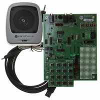
Figure 3-2 ISD-ES15100_USB
Table 3-1 EV Board Configuration
ith Read_Status because this command i
Function
EV board
xx
V Board
by USB; however,
unched, ISD15U
Publication Release Date: May 21, 2008
whenever VPE is launch, by
own microcontroller instead of the
to com
110 wo
y need
PRELIMINARY
gro
ble
mand ISD15100 at the
J17 & J21 are installed to
de-select the daughter
card.
Jumper is installed on 1-2
to select crystal as the
clock source.
Configured as MICIN
(differential input).
und. If
n’t do anything.
to poll RDY/BSYB pin for
at J19 (P).
s always needed for
Revision 151.003
users intend to
Default
21
Related parts for ISD-ES15100_USB
Image
Part Number
Description
Manufacturer
Datasheet
Request
R

Part Number:
Description:
Manufacturer:
Nuvoton Technology Corporation of America
Datasheet:
Part Number:
Description:
Manufacturer:
Nuvoton Technology Corporation of America
Datasheet:
Part Number:
Description:
Manufacturer:
Nuvoton Technology Corporation of America
Datasheet:
Part Number:
Description:
Manufacturer:
Nuvoton Technology Corporation of America
Datasheet:
Part Number:
Description:
Manufacturer:
Nuvoton Technology Corporation of America
Datasheet:
Part Number:
Description:
Manufacturer:
Nuvoton Technology Corporation of America
Datasheet:
Part Number:
Description:
Manufacturer:
Nuvoton Technology Corporation of America
Datasheet: