ISD-ES15100_USB Nuvoton Technology Corporation of America, ISD-ES15100_USB Datasheet - Page 16
ISD-ES15100_USB
Manufacturer Part Number
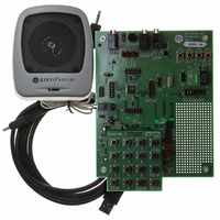
ISD-ES15100_USB
Description
BOARD EVALUATION USB FOR I15100
Manufacturer
Nuvoton Technology Corporation of America
Series
ChipCorder®r
Specifications of ISD-ES15100_USB
Main Purpose
Audio, Voice Record/Playback
Embedded
No
Utilized Ic / Part
ISD15102, 04, 08, 16, 32
Primary Attributes
ASIC, 2 ~ 16 Minutes, Up to 48kHz, Class D Amp, Line/Digital/Mic Input
Secondary Attributes
Graphic User Interface
Lead Free Status / RoHS Status
Not applicable / Not applicable


2.7
Memory Map is the last step to generate the programming file to be burned into the ISD15100
memory. The programming file is a binary file with mem extension. In this screen users will see how
each VP, VM, and message is assigned an address and/or an index. To activate the process, click on
‘Create Programming File’ (A). On the left hand side the memory map (B) is shown.
On the right hand side, the Memory Protection (C) decides how you want the memory contents
protected. ISD15100 provides three kinds of protection mechanisms:
If both Chip Erase Protect (CEP) and Write Protect (WP) are checked, it will lock the content from
beginning of the memory to PMP, preventing ISD15100 from any further modification.
The check boxes under ‘Project Information’ (D) allow users to add project information to the
programming file. If you check the users comment box, whatever you type in the comment window, it
will be appended to the end of the project information.
If the EV board is connected to PC, the ‘Burn Device’ button (E) will be effective. Once the
programming file is created, users can click on ‘Burn Device’ so that VPE will first chip-erase the
ISD15100 and then download the programming file into the ISD15100.
Please note that ‘Date’ (F) is part of the project, so clicking on the ‘Create Programming File’ (A) may
change the project contents even though users don’t change anything. When users open an existing
project, the memory map will be loaded automatically.
•
•
•
•
Memory Map
Update:
Read Protection:
Write Protection:
Chip-Erase Protection:
o
o
o
o
CFG0-CFG17 become active. In this way a path can be set up and applied at the
same instant to prevent disturbance on the analog path. (Write Only)
Once enabled, digital-read command is not effective in those protected area.
Once enabled, digital-write and memory-erase commands are not effective in those
protected area.
Once enabled, chip-erase command is not effective.
When a one is written to this bit and ‘Immediately Update’ is zero, configuration
Figure 2-11 Configuration
Publication Release Date: May 21, 2008
PRELIMINARY
Revision 151.003
16
Related parts for ISD-ES15100_USB
Image
Part Number
Description
Manufacturer
Datasheet
Request
R

Part Number:
Description:
Manufacturer:
Nuvoton Technology Corporation of America
Datasheet:
Part Number:
Description:
Manufacturer:
Nuvoton Technology Corporation of America
Datasheet:
Part Number:
Description:
Manufacturer:
Nuvoton Technology Corporation of America
Datasheet:
Part Number:
Description:
Manufacturer:
Nuvoton Technology Corporation of America
Datasheet:
Part Number:
Description:
Manufacturer:
Nuvoton Technology Corporation of America
Datasheet:
Part Number:
Description:
Manufacturer:
Nuvoton Technology Corporation of America
Datasheet:
Part Number:
Description:
Manufacturer:
Nuvoton Technology Corporation of America
Datasheet: