CPC5621-EVAL-RDL Clare, CPC5621-EVAL-RDL Datasheet - Page 5
CPC5621-EVAL-RDL
Manufacturer Part Number
CPC5621-EVAL-RDL
Description
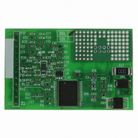
LITELINK III EVALUATION BOARD
Manufacturer
Clare
Series
LITELINK® IIIr
Specifications of CPC5621-EVAL-RDL
Main Purpose
Telecom, Isolation Solution
Embedded
No
Utilized Ic / Part
CPC5621
Primary Attributes
Full-Wave Ringing Detection Phone Line Interface
Secondary Attributes
Resistive AC Termination
Lead Free Status / RoHS Status
Lead free / RoHS Compliant
Other names
CLA164
CPC5621EVAL-RDL
CPC5621EVAL-RDL


1.3 Pin Description
R04
1
2
3
4
5
6
7
8
9
10 CID
11 RX-
12 RX+
13 SNP+
14 SNP-
15 RXF
16 RX
17 VDDL
18 RXS
19 RPB
20 BR-
21 ZDC
22 DCS2
23 DCS1
24 NTF
25 GAT
26 NTS
27 BR-
28 TXSL
29 ZNT
30 ZTX
31 TXF
32 REFL
Pin
VDD
TXSM
TX-
TX+
TX
MODE
GND
OH
RING
Name
Function
Low-voltage (CPE) side power supply
Transmit summing junction
Negative differential transmit signal to DAA
from low-voltage side
Positive differential transmit signal to DAA from
low-voltage side
Transmit differential amplifier output
When asserted low, changes gain of TX path
(-7 dB) and RX path (+7 dB) to accommodate
reactive termination networks
Low-voltage (CPE) side analog ground
Assert logic low for off-hook operation
Ringing Detect Output
Assert logic low while on hook to allow CID
information to be passed to the RX+ and RX-
output pins.
Negative differential analog signal received
from the telephone line. Must be AC coupled
with 0.1 μF.
Positive differential analog signal received from
the telephone line. Must be AC coupled with
0.1 μF.
Positive differential snoop input
Negative differential snoop input
Receive photodiode amplifier output
Receive photodiode summing junction
Power supply for line side, regulated from tip
and ring.
Receive isolation amp summing junction
Receive LED pre-bias current set
Bridge rectifier return
Electronic inductor DCR/current limit
DC feedback output
V to I slope control
Network amplifier feedback
External MOSFET gate control
Receive signal input
Bridge rectifier return
Transmit photodiode summing junction
Receiver impedance set
Transmit transconductance gain set
Transmit photodiode amplifier output
1.25 V
DC
reference
www.clare.com
Figure 2. Pinout
10
11
12
13
14
15
16
1
2
3
4
5
6
7
8
9
V
TXSM
TX-
TX+
TX
MODE
GND
OH
RING
CID
RX-
RX+
SNP+
SNP-
RXF
RX
DD
CPC5620/CPC5621
DCS1
DCS2
REFL
TXSL
ZDC
RPB
RXS
ZNT
NTS
NTF
V
TXF
ZTX
GAT
BR-
BR-
DDL
32
31
30
29
28
27
26
25
24
23
22
21
20
19
18
17
5
Related parts for CPC5621-EVAL-RDL
Image
Part Number
Description
Manufacturer
Datasheet
Request
R

Part Number:
Description:
LITELINK III EVALUATION BOARD
Manufacturer:
Clare
Datasheet:

Part Number:
Description:
Clare Solar Cells
Manufacturer:
Clare, Inc.
Datasheet:
Part Number:
Description:
Clare Solar Cells
Manufacturer:
Clare, Inc.
Datasheet:
Part Number:
Description:
4 Pin SOP OptoMOS Relay
Manufacturer:
CLARE [Clare, Inc.]
Datasheet:

Part Number:
Description:
MOSFET N-CH 350V 5MA SOT-223
Manufacturer:
Clare
Datasheet:
Part Number:
Description:
MOSFET N-CH 350V 5MA SOT-223
Manufacturer:
Clare
Datasheet:

Part Number:
Description:
IC DRVR PROGRAMMABLE 16-SOIC
Manufacturer:
Clare
Datasheet:

Part Number:
Description:
IC PHONE LINE MONITOR 8-SOIC
Manufacturer:
Clare
Datasheet:

Part Number:
Description:
IC LITELINK III FULL RING 32SOIC
Manufacturer:
Clare
Datasheet:

Part Number:
Description:
LITELINK III PHONE LINE 32SOIC
Manufacturer:
Clare
Datasheet:

Part Number:
Description:
RELAY OPTO TELCOM 12OMA 8-DIP
Manufacturer:
Clare
Datasheet: