STEVAL-IPT002V1 STMicroelectronics, STEVAL-IPT002V1 Datasheet - Page 17
STEVAL-IPT002V1
Manufacturer Part Number
STEVAL-IPT002V1
Description
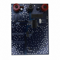
BOARD EVAL SMART CARD
Manufacturer
STMicroelectronics
Specifications of STEVAL-IPT002V1
Main Purpose
Memory, Smart Card
Embedded
No
Utilized Ic / Part
ST8024
Primary Attributes
New Digital Systems (NDS) Compatible
Secondary Attributes
Short-Circuit & Thermal Protection
Product
Power Management Modules
Silicon Manufacturer
ST Micro
Silicon Core Number
ST8024
Kit Application Type
Interface
Application Sub Type
Smart Card Interface
Kit Contents
Board CD Docs
Lead Free Status / RoHS Status
Lead free / RoHS Compliant
Other names
497-8939
Available stocks
Company
Part Number
Manufacturer
Quantity
Price
Company:

Part Number:
STEVAL-IPT002V1
Manufacturer:
STMicroelectronics
Quantity:
1


5.2.2
5.2.3
5.3
Figure 4.
With an external divider on pin PORADJ
If an external resistor bridge is connected to pin PORADJ (R1 and R2 in
following occurs:
Input PORADJ is biased internally with a pull-down current source of 4 µA which is removed
when the voltage on pin PORADJ exceeds 1 V.
This ensures that after detection of the external bridge by the IC during power-on, the input
current on pin PORADJ does not cause inaccuracy of the bridge voltage.
The minimum threshold voltage should be higher than 2 V. The maximum threshold voltage
may be up to V
Application examples
The voltage supervisor is used as power-on reset and as supply dropout detection during a
card session. Supply dropout detection is to ensure that a proper deactivation sequence is
followed before the voltage is too low. For the internal voltage supervisor to function, the
system microcontroller should operate down to 2.35 V to ensure a proper deactivation
sequence. If this is not possible, external resistor values can be chosen to overcome the
problem.
Clock circuitry
The card clock signal (CLK) is derived from a clock signal input to pin XTAL1 or from a
crystal operating at up to 26 MHz connected between pins XTAL1 and XTAL2.
The clock frequency can be f
is made via inputs CLKDIV1 and CLKDIV2 (see
– The internal threshold voltage V
– The reset pulse width t
V
V
where V
th2(ext)(rise)
th2(ext)(fall)
hysteresis, therefore:
Voltage supervisor
bridge
DD
= (1 + R1/R2) x (V
= (1 + R1/R2) x (V
.
= 1.25 V typ. and V
XTAL
W
is doubled to approximately 16 ms.
, 1/2 x f
bridge -
bridge
hys(ext)
th2
XTAL
+ V
is overridden by the external voltage and by the
V
hys(ext)
, 1/4 x f
hys(ext)
= 60 mV typ.
Table
/2)
/2)
XTAL
21).
or 1/8 x f
XTAL
. Frequency selection
Figure
1), then the
17/31
Related parts for STEVAL-IPT002V1
Image
Part Number
Description
Manufacturer
Datasheet
Request
R

Part Number:
Description:
BOARD DEMO TFT DISPLAY STR91
Manufacturer:
STMicroelectronics
Datasheet:

Part Number:
Description:
BOARD EVAL FOR MEMS SENSORS
Manufacturer:
STMicroelectronics
Datasheet:

Part Number:
Description:
KIT DEV STARTER ST10F276Z5
Manufacturer:
STMicroelectronics
Datasheet:

Part Number:
Description:
BOARD EVAL HDMI $ VIDEO SWITCH
Manufacturer:
STMicroelectronics
Datasheet:

Part Number:
Description:
BOARD DEMO ACCELEROMETER DIL24
Manufacturer:
STMicroelectronics
Datasheet:

Part Number:
Description:
BOARD STLM75/STDS75/ST72F651
Manufacturer:
STMicroelectronics
Datasheet:

Part Number:
Description:
EVAL BOARD 3AXIS MEMS ACCELLRMTR
Manufacturer:
STMicroelectronics
Datasheet:

Part Number:
Description:
BOARD EVAL 8BIT MICRO + TDE1708
Manufacturer:
STMicroelectronics
Datasheet:

Part Number:
Description:
EVAL BOARD A/D TS4657
Manufacturer:
STMicroelectronics
Datasheet:

Part Number:
Description:
BOARD ADAPTER 20DIP LIS3LV02DL
Manufacturer:
STMicroelectronics
Datasheet:
Part Number:
Description:
STMicroelectronics [RIPPLE-CARRY BINARY COUNTER/DIVIDERS]
Manufacturer:
STMicroelectronics
Datasheet:
Part Number:
Description:
STMicroelectronics [LIQUID-CRYSTAL DISPLAY DRIVERS]
Manufacturer:
STMicroelectronics
Datasheet:
Part Number:
Description:
BOARD EVAL FOR MEMS SENSORS
Manufacturer:
STMicroelectronics
Datasheet: