STEVAL-IFP007V1 STMicroelectronics, STEVAL-IFP007V1 Datasheet - Page 14
STEVAL-IFP007V1
Manufacturer Part Number
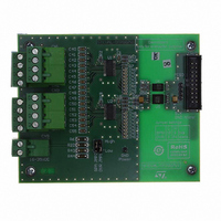
STEVAL-IFP007V1
Description
BOARD EVAL BASED ON SCLT3-8
Manufacturer
STMicroelectronics
Specifications of STEVAL-IFP007V1
Main Purpose
Interface, Digital Signal Termination
Embedded
No
Utilized Ic / Part
SCLT3-8
Primary Attributes
8 Channel Optical Isolation
Secondary Attributes
SPI Interface
Processor To Be Evaluated
SCLT3
Data Bus Width
16 bit
Interface Type
SPI
Operating Supply Voltage
24 V
Lead Free Status / RoHS Status
Lead free / RoHS Compliant
Other names
497-9045


Functional description
2.7.2
2.7.3
14/33
Figure 11. UVA circuit block diagram
The power supply diagnostics help to determine if the input state is really low or if some
power bus failure is damaging the quality of this state signal.
Over temperature alarm
A temperature sensor, equivalent to a diode drop voltage, is placed on the power section of
the SCLT in order to sense its operating junction temperature.
This protection allows abnormal temperature cases to be detected. The input reverse
polarity generates higher current in the inputs, more than twice that shown in the application
section, and a maintenance action allows the overall system and functional reliability to be
improved.
The alarm signal /OTA is enabled, low state active, when the junction temperature is higher
than the activation threshold T
temperature falls below the threshold T
The over temperature detection does not lead to the SCLT internal shutdown but generates
an alarm OTA that is transmitted through the SPI on control bit #6. So, it is up to the I/O
controller to launch the appropriate action on the system to reduce the constraint in the I/O
module.
Figure 12. Logic behavior of the OTA and UVA alarm control bits
Parity checksum bits calculation and transfer
The aim of the parity checksum bit is to detect one error in the transferred SPI word. Several
parity checksum bits are generated and transmitted through the SPI on the control bit #2 to
#5.
Transmission errors can occur because of the ESD / surge effects or the indirect effects of
EFT burst tests beyond the required levels.
T
T
T
OFF
OFF
OFF
R
R
R
R
PD
PD
S
S
V
V
CC
CC
T
T
T
ON
ON
ON
ON
Doc ID 15191 Rev 3
COM
COM
V
V
CS
CS
, 150 °C typical, and it is disabled when the junction
P
P
ESD
ESD
OFF,
V
V
BG
BG
135 °C typical as shown in
SCLT3-8
SCLT3-8
1ms delay filter
1ms delay filter
V
V
V
CCON
CCON
CCON
/UVA
/UVA
V
V
V
Figure
CCOFF
CCOFF
CCOFF
12.
SCLT3-8BT8
Related parts for STEVAL-IFP007V1
Image
Part Number
Description
Manufacturer
Datasheet
Request
R

Part Number:
Description:
BOARD EVAL SPZB260 MOD FOR STR9
Manufacturer:
STMicroelectronics
Datasheet:

Part Number:
Description:
BOARD EVAL EXTENSION SN250
Manufacturer:
STMicroelectronics
Datasheet:

Part Number:
Description:
BOARD EVAL AB-54003L-512
Manufacturer:
STMicroelectronics
Datasheet:

Part Number:
Description:
BOARD REF DESIGN RF DMOS PWR AMP
Manufacturer:
STMicroelectronics
Datasheet:

Part Number:
Description:
BOARD EVAL PWR AMP AB-84008L-470
Manufacturer:
STMicroelectronics
Datasheet:

Part Number:
Description:
BOARD EVAL FOR STM32F103XX
Manufacturer:
STMicroelectronics
Datasheet:

Part Number:
Description:
BOARD EVAL AB-54003L-512
Manufacturer:
STMicroelectronics
Datasheet:

Part Number:
Description:
BOARD SMART PLUG STM32 SPZB260PR
Manufacturer:
STMicroelectronics
Datasheet:

Part Number:
Description:
BOARD DEMO BLUETOOTH SPBT2532C2
Manufacturer:
STMicroelectronics
Datasheet:
Part Number:
Description:
ZIGBEE USB DONGLE EVAL KIT
Manufacturer:
STMicroelectronics
Datasheet:
Part Number:
Description:
STMicroelectronics [RIPPLE-CARRY BINARY COUNTER/DIVIDERS]
Manufacturer:
STMicroelectronics
Datasheet:
Part Number:
Description:
STMicroelectronics [LIQUID-CRYSTAL DISPLAY DRIVERS]
Manufacturer:
STMicroelectronics
Datasheet:

Part Number:
Description:
BOARD EVAL FOR MEMS SENSORS
Manufacturer:
STMicroelectronics
Datasheet: