STEVAL-SCM001V1 STMicroelectronics, STEVAL-SCM001V1 Datasheet - Page 12
STEVAL-SCM001V1
Manufacturer Part Number
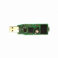
STEVAL-SCM001V1
Description
KIT DEMO DONGLE RTC M41T62/ST7
Manufacturer
STMicroelectronics
Datasheets
1.M41T62Q6F.pdf
(43 pages)
2.STEVAL-SCM001V1.pdf
(4 pages)
3.STEVAL-SCM001V1.pdf
(4 pages)
Specifications of STEVAL-SCM001V1
Design Resources
STEVAL-SCM001V1 Gerber Files STEVAL-SCM001V1/RTC Schematic
Main Purpose
Timing, ARM7 based RTC USB Dongle
Embedded
Yes, MCU, 8-Bit
Utilized Ic / Part
M41T62, ST72F651
Primary Attributes
RTC (Real-Time Clock) and Mass Storage Capabilities
Secondary Attributes
Graphical User Interface, USB Interface
Silicon Manufacturer
ST Micro
Silicon Core Number
M41T62 And ST72651AR6
Kit Application Type
Clock & Timing
Application Sub Type
RTC Dongle
Kit Contents
Board CD Docs
Lead Free Status / RoHS Status
Lead free / RoHS Compliant
Other names
497-5684
Available stocks
Company
Part Number
Manufacturer
Quantity
Price
Company:

Part Number:
STEVAL-SCM001V1
Manufacturer:
STMicroelectronics
Quantity:
135


Operation
2
2.1
2.1.1
2.1.2
2.1.3
12/43
Operation
The M41T6x clock operates as a slave device on the serial bus. Access is obtained by
implementing a start condition followed by the correct slave address (D0h). The 16 bytes
contained in the device can then be accessed sequentially in the following order:
●
●
●
●
●
●
●
●
●
●
●
●
2-wire bus characteristics
The bus is intended for communication between different ICs. It consists of two lines: a bi-
directional data signal (SDA) and a clock signal (SCL). Both the SDA and SCL lines must be
connected to a positive supply voltage via a pull-up resistor.
The following protocol has been defined:
●
●
●
Accordingly, the following bus conditions have been defined:
Bus not busy
Both data and clock lines remain high.
Start data transfer
A change in the state of the data line, from high to low, while the clock is high, defines the
START condition.
Stop data transfer
A change in the state of the data line, from low to high, while the clock is high, defines the
STOP condition.
1
2
3
4
5
6
7
8
9
10
11
16th byte: flags register
Data transfer may be initiated only when the bus is not busy.
During data transfer, the data line must remain stable whenever the clock line is high.
Changes in the data line, while the clock line is high, will be interpreted as control
signals.
st
nd
rd
th
th
th
th
th
th
th
th
byte: tenths/hundredths of a second register
byte: hours register
byte: square wave/day register
byte: date register
byte: century/month register
byte: year register
byte: calibration register
byte: minutes register
byte: seconds register
byte: watchdog register
- 15
th
bytes: alarm registers
Doc ID 10397 Rev 15
M41T62/63/64/65
Related parts for STEVAL-SCM001V1
Image
Part Number
Description
Manufacturer
Datasheet
Request
R

Part Number:
Description:
DEMO BOARD FOR SINGLE OP-AMPS
Manufacturer:
STMicroelectronics
Datasheet:

Part Number:
Description:
KIT EVAL USB/RS232 ST7
Manufacturer:
STMicroelectronics
Datasheet:

Part Number:
Description:
BOARD EVAL HDMI $ VIDEO SWITCH
Manufacturer:
STMicroelectronics
Datasheet:

Part Number:
Description:
BOARD DEMO MEMS LPR430AL
Manufacturer:
STMicroelectronics
Datasheet:

Part Number:
Description:
BOARD EVALUATION FOR LPR550AL
Manufacturer:
STMicroelectronics
Datasheet:

Part Number:
Description:
EVAL BOARD A/D TS4657
Manufacturer:
STMicroelectronics
Datasheet:

Part Number:
Description:
BOARD & REF DESIGN
Manufacturer:
STMicroelectronics
Datasheet:

Part Number:
Description:
BOARD EVAL S-TOUCH STM32
Manufacturer:
STMicroelectronics
Datasheet:

Part Number:
Description:
BOARD ADAPTER LPR403AL DIL24
Manufacturer:
STMicroelectronics
Datasheet:

Part Number:
Description:
BOARD DEMO LPR4150AL GYROSCOPE
Manufacturer:
STMicroelectronics
Datasheet:
Part Number:
Description:
STMicroelectronics [RIPPLE-CARRY BINARY COUNTER/DIVIDERS]
Manufacturer:
STMicroelectronics
Datasheet:
Part Number:
Description:
STMicroelectronics [LIQUID-CRYSTAL DISPLAY DRIVERS]
Manufacturer:
STMicroelectronics
Datasheet:

Part Number:
Description:
BOARD EVAL FOR MEMS SENSORS
Manufacturer:
STMicroelectronics
Datasheet: