CDB8420 Cirrus Logic Inc, CDB8420 Datasheet - Page 3
CDB8420
Manufacturer Part Number
CDB8420
Description
EVALUATION BOARD FOR CS8420
Manufacturer
Cirrus Logic Inc
Datasheet
1.CDB8420.pdf
(14 pages)
Specifications of CDB8420
Main Purpose
Audio, Sample Rate Converter
Embedded
Yes, MCU, 8-Bit
Utilized Ic / Part
CS8420
Primary Attributes
Sample Rate Converter with Digital Audio Transmitter and Receiver
Secondary Attributes
44.1, 48, 96 kHz Output Sample Rates, AES/EBU, S/PDIF, EIAJ-340, GUI
Description/function
Audio DSPs
Operating Supply Voltage
5 V
Product
Audio Modules
Silicon Manufacturer
Cirrus Logic
Silicon Core Number
CS8420
Kit Application Type
Data Converter
Application Sub Type
Sample Rate Converter (SRC)
Kit Contents
Evaluation Board
Rohs Compliant
No
For Use With/related Products
CS8420
Lead Free Status / RoHS Status
Contains lead / RoHS non-compliant
Lead Free Status / RoHS Status
Lead free / RoHS Compliant, Contains lead / RoHS non-compliant
Other names
598-1782


1.
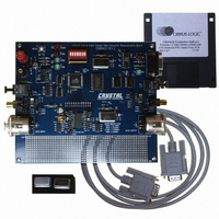
The CDB8420 evaluation board contains a CS8420
and the supporting circuitry necessary for it to op-
erate. The input and output options include AES3
and S/PDIF in optical and coaxial formats. In soft-
ware mode, the control registers of the CS8420 are
set by an Atmel AVR RISC micro-controller. A
Windows 98 based program communicates with
the micro through an RS232 port to control the con-
figuration.
1.1
The features and functions of the CS8420 are de-
scribed in its data sheet.
1.2
The functions of the board are controlled by an At-
mel AVR RISC micro-controller. The board is
equipped with 512 kilobytes of static RAM so that
Channel Status and User bits from the AES stream
may be captured and uploaded to the host PC. The
micro-controller communicates with the CS8420
through its SPI port. The Atmel AVR RISC micro-
controller may be bypassed in order to utilize an
external micro-controller through header J10. Ad-
ditional software development tools and applica-
tions information for the Atmel micro-controller
are available at http://www.atmel.com.
1.3
There are two crystal oscillators on the board, both
are mounted in pin sockets that allow them to be re-
DS245DB4
OVERVIEW
CS8420
Micro-Controller and Memory
Crystal Oscillators
placed. The oscillator labeled U10 provides the 6
MHz clock for the micro-controller and should not
be changed.
U3 is the oscillator that provides the Output Master
Clock for the CS8420. The board is shipped with a
12.288 MHz crystal oscillator stuffed at U3 which
sets the output sampling rate to 48 kHz.
Oscillators are also provided for the frequencies of
11.2896 and 24.576 MHz. These allow the SRC to
be operated at output sampling frequencies of 44.1
and 96 kHz.
1.4
The RS232 port on the upper right hand side of the
board should be connected to the serial port of the
PC running the CDB8420 control software. Follow
the software instructions to properly configure the
serial port for use with the evaluation board.
1.5
LEDs D8 and D9 on the upper right hand corner of
the board allow the user to determine when data is
being transmitted over the RS232 link. The red
LED D4 is the reset indicator and the red LED D1
is connected to the RERR pin of the CS8420. The
two remaining LEDs on the board are not currently
of use to the end user.
RS232 Port
LED Function Indicators
CDB8420
3
Related parts for CDB8420
Image
Part Number
Description
Manufacturer
Datasheet
Request
R

Part Number:
Description:
Development Kit
Manufacturer:
Cirrus Logic Inc
Datasheet:
Part Number:
Description:
Development Kit
Manufacturer:
Cirrus Logic Inc
Datasheet:


Part Number:
Description:
High-efficiency PFC + Fluorescent Lamp Driver Reference Design
Manufacturer:
Cirrus Logic Inc
Datasheet:
Part Number:
Description:
Development Kit
Manufacturer:
Cirrus Logic Inc
Datasheet:
Part Number:
Description:
Development Kit
Manufacturer:
Cirrus Logic Inc
Datasheet:

Part Number:
Description:
Development Kit
Manufacturer:
Cirrus Logic Inc
Datasheet:
Part Number:
Description:
Development Kit
Manufacturer:
Cirrus Logic Inc
Datasheet:
Part Number:
Description:
Development Kit
Manufacturer:
Cirrus Logic Inc
Datasheet:
Part Number:
Description:
Development Kit
Manufacturer:
Cirrus Logic Inc
Datasheet:

Part Number:
Description:
EVALUATION BOARD FOR CS8427
Manufacturer:
Cirrus Logic Inc
Datasheet:

Part Number:
Description:
BOARD EVAL FOR CS8416 RCVR
Manufacturer:
Cirrus Logic Inc
Datasheet:

Part Number:
Description:
KIT DEVELOPMENT EP9315 ARM9
Manufacturer:
Cirrus Logic Inc
Datasheet:

Part Number:
Description:
KIT DEVELOPMENT EP9302 ARM9
Manufacturer:
Cirrus Logic Inc
Datasheet:

Part Number:
Description:
KIT DEVELOPMENT EP9307 ARM9
Manufacturer:
Cirrus Logic Inc
Datasheet: