CDB8416 Cirrus Logic Inc, CDB8416 Datasheet - Page 4
CDB8416
Manufacturer Part Number
CDB8416
Description
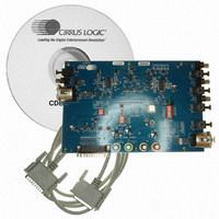
BOARD EVAL FOR CS8416 RCVR
Manufacturer
Cirrus Logic Inc
Datasheet
1.CDB8416.pdf
(26 pages)
Specifications of CDB8416
Main Purpose
Audio, Audio Processing
Embedded
Yes, Other
Utilized Ic / Part
CS8406, CS8416
Primary Attributes
Digital Audio Transmitter and Receiver
Secondary Attributes
Graphic User Interface, AES/EBU, S/PDIF and EIAJ-340
Product
Audio Modules
Silicon Manufacturer
Cirrus Logic
Silicon Core Number
CS8416
Kit Application Type
Communication & Networking
Application Sub Type
Digital Audio Receiver
Kit Contents
Board
Rohs Compliant
No
Lead Free Status / RoHS Status
Contains lead / RoHS non-compliant
Lead Free Status / RoHS Status
Lead free / RoHS Compliant, Contains lead / RoHS non-compliant
Other names
598-1017


1. OVERVIEW
The CDB84166 evaluation board contains a
CS8416 and a CS8406 and the supporting circuitry
necessary to operate them. The board provides bal-
anced XLR and unbalanced optical and coaxial in-
puts and outputs as outlined in the AES3 and
IEC60958 standards. In Software Mode, the con-
trol registers of the CS8416 and CS8406 are set by
a Windows based program through the parallel port
of a PC.
1.1
The features and functions of the CS8416 and the
CS8406 are described in their respective data
sheets.
1.2
To use the CS8416 and CS8406 on the board in
Software Mode, the parallel port on the upper right
hand side of the board should be connected to the
parallel port of the PC running the CDB8416 con-
trol software.
1.3
The left edge of the board is occupied by a row of
serial digital audio input connectors. In either
Hardware or Software Mode the user must select
which inputs are to be used via the switch setting,
INPUT, on switch S3.
Set the switch to the open position to select the
XLR balanced input which will use the RXP1 and
RXN inputs of the CS8416.
Set the switch to the closed position to select the
optical/coaxial unbalanced inputs which will use
the RXP0 and RXP2 through RXP7 inputs of the
CS8416. This will AC couple the RXN input to
GND. Note that in Hardware Mode, only RXP0
through RXP3 on the CS8416 are available for use.
To select between the inputs in Hardware Mode,
use the RXSEL0 and RXSEL1 switches on S3.
4
CS8416 and CS8406
Parallel Port
Serial Digital Audio Inputs
1.4
The right edge of the board is occupied by the serial
digital audio outputs. The optical S/PDIF output is
always enabled. The user may also choose to en-
able either the coaxial S/PDIF output or the XLR
AES3 output via jumper J11. These outputs are
transformer coupled.
1.5
Header J18 is provided so the user may access the
three wire serial audio ports of the receiver and
transmitter. The purpose of this port is to allow the
user to connect external circuitry such as a DAC,
ADC, or DSP to the receiver and transmitter. Sig-
nals going into or out of these headers should be
operated at VL+.
Setting switch S1-M/S in the open position sets the
CS8416 as the master and the CS8406 as slave for
LRCK and SCLK. Setting switch S1-M/S in the
closed position sets the CS8406 as the master and
the CS8416 as slave for LRCK and SCLK.
Setting switch S3-8416_PCM to the open position
will turn off all of the input/output buffers for the
CS8416. Setting switch S4-8406_PCM to the open
position will turn off all of the input/output buffers
for the CS8406. These switches allow the user to
independently set the input and output for the
CS8416 and CS8406.
1.6
Oscillator Y1 provides the System Clock (OMCK)
for the CS8416. The crystal oscillator on the board
is mounted in pin sockets that allow it to be re-
moved or replaced. The board is shipped with a
12.288 MHz crystal oscillator stuffed at Y1, setting
the output sampling rate to 48 kHz. Please refer to
the CS8416 data sheet for details on OMCK opera-
tion.
Serial Digital Audio Outputs
Three-wire (PCM) Serial Audio
Input and Output
Crystal Oscillators
CDB8416
DS578DB3
Related parts for CDB8416
Image
Part Number
Description
Manufacturer
Datasheet
Request
R

Part Number:
Description:
Development Kit
Manufacturer:
Cirrus Logic Inc
Datasheet:
Part Number:
Description:
Development Kit
Manufacturer:
Cirrus Logic Inc
Datasheet:


Part Number:
Description:
High-efficiency PFC + Fluorescent Lamp Driver Reference Design
Manufacturer:
Cirrus Logic Inc
Datasheet:
Part Number:
Description:
Development Kit
Manufacturer:
Cirrus Logic Inc
Datasheet:
Part Number:
Description:
Development Kit
Manufacturer:
Cirrus Logic Inc
Datasheet:

Part Number:
Description:
Development Kit
Manufacturer:
Cirrus Logic Inc
Datasheet:
Part Number:
Description:
Development Kit
Manufacturer:
Cirrus Logic Inc
Datasheet:
Part Number:
Description:
Development Kit
Manufacturer:
Cirrus Logic Inc
Datasheet:
Part Number:
Description:
Development Kit
Manufacturer:
Cirrus Logic Inc
Datasheet:

Part Number:
Description:
EVALUATION BOARD FOR CS8427
Manufacturer:
Cirrus Logic Inc
Datasheet:

Part Number:
Description:
EVALUATION BOARD FOR CS8420
Manufacturer:
Cirrus Logic Inc
Datasheet:

Part Number:
Description:
KIT DEVELOPMENT EP9315 ARM9
Manufacturer:
Cirrus Logic Inc
Datasheet:

Part Number:
Description:
KIT DEVELOPMENT EP9302 ARM9
Manufacturer:
Cirrus Logic Inc
Datasheet:

Part Number:
Description:
KIT DEVELOPMENT EP9307 ARM9
Manufacturer:
Cirrus Logic Inc
Datasheet: