IS-DEV KIT-6C NKK Switches, IS-DEV KIT-6C Datasheet - Page 4
IS-DEV KIT-6C
Manufacturer Part Number
IS-DEV KIT-6C
Description
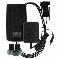
KIT DEV LCD 64X32 COMPACT SWITCH
Manufacturer
NKK Switches
Series
SmartSwitch™r
Specifications of IS-DEV KIT-6C
Main Purpose
Switches with Programmable Display
Utilized Ic / Part
IS15DSBFP4RGB
Primary Attributes
2 Compact Switches, PC Board with Flash Memory
Secondary Attributes
Power and Programming Connections
Description/function
SMARTSWITCH Development Kit
For Use With
360-2431 - SERIAL CBL RJ11-DB9 FOR DEV KIT360-2430 - POWER SUPPLY 240VAC FOR DEV KIT360-2429 - POWER SUPPLY 120VAC FOR DEV KIT
Lead Free Status / RoHS Status
Not applicable / Not applicable
Embedded
-
Lead Free Status / Rohs Status
Lead free / RoHS Compliant
For Use With/related Products
Smart Switch - High Resolution
Other names
360-2337


7850 East Gelding Drive • Scottsdale, AZ 85260-3420
4. Operational Overview
Power-up Sequence:
Upon power up, the controller checks the position of the Mode Select Switch. The switch position has to match
the logic board/switches connected. The “High res” position will work only for LCD 64x32 switches/displays
while the “Standard res” position will work only for LCD 36x24 switches/displays.
Note: Setting the switch to a different setting than the Logic Board type may damage the assembly.
LED Brightness Adjustment Mode:
The controller will then allow the backlight brightness to be adjusted. Press the left hand switch to make both
LED modules dimmer. Press the right hand switch to make both LED modules brighter.
Main Operational Mode:
After a few seconds of user inactivity the controller will move into the main operations mode where the switch
on the left displays the image at the user’s first preset address. The right hand switch will display the image at
the user’s second preset address. The controller will then respond to a switch actuation or a timer expiration as
set by the user preset attributes.
Addresses:
A one byte value ranging from 01H to FFH representing the 255 memory.
Attribute Block for 64x32 Resolution Switches
IS-Dev Kit-5 and IS-Dev Kit-6 Users Manual A.doc
Toll Free 1.877.2BUYNKK (877.228.9655) • Phone 480.991.0942 • Fax 480.998.1435
IS-Dev Kit-5 and IS-Dev Kit-6 Users
A block of 8 bytes.
Byte
www.nkkswitches.com • Email engineering@nkkswitches.com
1
2
3
4
5
6
7
8
Address for LCD Module #1
when switch is pressed.
Address for LCD Module #2
when switch is pressed
Address for LCD Module #1
when the timer is expired.
Address for LCD Module #2
when the timer is expired.
Value for TIMER 1
Value for TIMER 2
LED CODE for on cycle
LED CODE for off cycle
Manual
Description
Page 4 of 24
1209
Related parts for IS-DEV KIT-6C
Image
Part Number
Description
Manufacturer
Datasheet
Request
R

Part Number:
Description:
SMARTSWITCH DEVELOPMENT KIT 5C
Manufacturer:
NKK Switches
Datasheet:

Part Number:
Description:
KIT DEV FOR LCD 64X32 SWITCH
Manufacturer:
NKK Switches
Datasheet:

Part Number:
Description:
KIT DEV FOR OLED DISPLAY
Manufacturer:
NKK Switches
Datasheet:

Part Number:
Description:
KIT DEV FOR OLED SWITCH
Manufacturer:
NKK Switches
Datasheet:

Part Number:
Description:
BOARD DEV 2RGB SW FLASH & PROGR
Manufacturer:
NKK Switches
Datasheet:

Part Number:
Description:
KIT DEV FOR LCD 64X32 DISPLAY
Manufacturer:
NKK Switches
Datasheet:

Part Number:
Description:
SMARTSWITCH DEVELOPMENT KIT 1
Manufacturer:
NKK Switches
Datasheet:

Part Number:
Description:
SMARTSWITCH DEVELOPMENT KIT 2
Manufacturer:
NKK Switches
Datasheet:

Part Number:
Description:
SMARTSWITCH DEVELOPMENT KIT 5
Manufacturer:
NKK Switches
Datasheet:

Part Number:
Description:
SMARTSWITCH DEVELOPMENT KIT 8
Manufacturer:
NKK Switches
Datasheet:

Part Number:
Description:
LED Displays PROGRAMMABLE SWITCH
Manufacturer:
NKK Switches

Part Number:
Description:
ON-OFF PLATE - SERIES -EMP
Manufacturer:
NKK Switches
Datasheet:

Part Number:
Description:
WRENCH SOCKET FOR KB SERIES PB
Manufacturer:
NKK Switches
Datasheet:

Part Number:
Description:
SWITCH TOGGLE DPST 25A SLDR 5PCS
Manufacturer:
NKK Switches
Datasheet:

Part Number:
Description:
SWITCH TOGGLE DPDT 15A SLDR 5PC
Manufacturer:
NKK Switches
Datasheet: