IS-DEV KIT-2 NKK Switches, IS-DEV KIT-2 Datasheet - Page 4
IS-DEV KIT-2
Manufacturer Part Number
IS-DEV KIT-2
Description
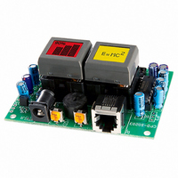
SMARTSWITCH DEVELOPMENT KIT 2
Manufacturer
NKK Switches
Series
SmartSwitch™r
Datasheet
1.IS-DEV_KIT-2.pdf
(15 pages)
Specifications of IS-DEV KIT-2
Main Purpose
Switches with Programmable Display
Utilized Ic / Part
SmartSwitch™LCD Switch
Primary Attributes
2 LCD Switches, PC Board with Flash Memory
Secondary Attributes
Up to 255 Pictures and Attributes
Description/function
SMARTSWITCH Development Kit
Architecture
Universal Communicator
Board Size
1.752 in x 0.965 in
Maximum Operating Temperature
+ 40 C
Minimum Operating Temperature
0 C
Operating Voltage
9 V
Supply Current
150 mA
For Use With
360-2431 - SERIAL CBL RJ11-DB9 FOR DEV KIT360-2430 - POWER SUPPLY 240VAC FOR DEV KIT360-2429 - POWER SUPPLY 120VAC FOR DEV KIT
Lead Free Status / RoHS Status
Not applicable / Not applicable
Embedded
-
Lead Free Status / Rohs Status
Lead free / RoHS Compliant
For Use With/related Products
Smart Switch - LCD Programmble Pushbutton Switches
Other names
360-2326


7850 East Gelding Drive • Scottsdale, AZ 85260-3420
2. Key Terms & Definitions
LCD Module
Host
Controller
Logic Board
Byte
Nibble/Hex digit
ASCII
Communication
format
Pointer
IS-Dev Kit-2 Users Manual A.doc
Toll Free 1.877.2BUYNKK (877.228.9655) • Phone 480.991.0942 • Fax 480.998.1435
NKK Switches SmartSwitch / SmartDisplay
Any computer, terminal, or other device that can communicate over RS232
line.
A PCB assembly that controls one or more logic boards and the switches
associated with them. It communicates with a host over the RS232 line.
A PCB assembly with “glue logic” for mounting switches. It is controlled by a
controller.
An eight bit hex value ranging from 00H to FFH (Decimal 0 to 255). The bit
format of a byte is: (B7 B6 B5 B4 B3 B2 B1 B0) where B7 is most significant
and bit B0 is least significant bit.
A four bit value ranging from 0H to FH. A byte consists of two nibbles.
A byte value representing a symbol.
There are two formats to transmit a byte:
1. Hex format - A hex byte is transmitted without any change to it. [xxH] will
2. ASCII format - Each nibble of the byte is converted to ASCII code and
One byte. There is a pointer for each LCD Module. The value of a pointer is
a virtual address that refers to the 255 storage locations in the EEPROM (01H
to FFH). Each location has image data LED data, and attribute data. The
controller finds the actual address from this virtual address and uses the data
for the LCD modules.
be used to denote this.
All commands and some data sent by using this format.
sent as a byte. [xxAH] will be used to denote this.
For example, the hex byte 5AH is transmitted in two bytes, 35H and 41H.
The ASCII value for 5 is 35H and the ASCII value for A is 41H.
All pointers, all addresses and most data are sent using this format.
www.nkkswitches.com • Email engineering@nkkswitches.com
IS-Dev Kit-2 Users Manual
Page 4 of 15
0110
Related parts for IS-DEV KIT-2
Image
Part Number
Description
Manufacturer
Datasheet
Request
R

Part Number:
Description:
SMARTSWITCH DEVELOPMENT KIT 5C
Manufacturer:
NKK Switches
Datasheet:

Part Number:
Description:
KIT DEV FOR LCD 64X32 SWITCH
Manufacturer:
NKK Switches
Datasheet:

Part Number:
Description:
KIT DEV LCD 64X32 COMPACT SWITCH
Manufacturer:
NKK Switches
Datasheet:

Part Number:
Description:
KIT DEV FOR OLED DISPLAY
Manufacturer:
NKK Switches
Datasheet:

Part Number:
Description:
KIT DEV FOR OLED SWITCH
Manufacturer:
NKK Switches
Datasheet:

Part Number:
Description:
BOARD DEV 2RGB SW FLASH & PROGR
Manufacturer:
NKK Switches
Datasheet:

Part Number:
Description:
KIT DEV FOR LCD 64X32 DISPLAY
Manufacturer:
NKK Switches
Datasheet:

Part Number:
Description:
SMARTSWITCH DEVELOPMENT KIT 1
Manufacturer:
NKK Switches
Datasheet:

Part Number:
Description:
SMARTSWITCH DEVELOPMENT KIT 5
Manufacturer:
NKK Switches
Datasheet:

Part Number:
Description:
SMARTSWITCH DEVELOPMENT KIT 8
Manufacturer:
NKK Switches
Datasheet:

Part Number:
Description:
LED Displays PROGRAMMABLE SWITCH
Manufacturer:
NKK Switches

Part Number:
Description:
ON-OFF PLATE - SERIES -EMP
Manufacturer:
NKK Switches
Datasheet:

Part Number:
Description:
WRENCH SOCKET FOR KB SERIES PB
Manufacturer:
NKK Switches
Datasheet:

Part Number:
Description:
SWITCH TOGGLE DPST 25A SLDR 5PCS
Manufacturer:
NKK Switches
Datasheet:

Part Number:
Description:
SWITCH TOGGLE DPDT 15A SLDR 5PC
Manufacturer:
NKK Switches
Datasheet: