OM6272,598 NXP Semiconductors, OM6272,598 Datasheet - Page 7
OM6272,598
Manufacturer Part Number
OM6272,598
Description
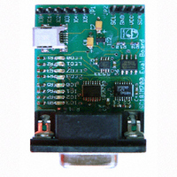
DEMO BOARD UART TO I2C
Manufacturer
NXP Semiconductors
Datasheet
1.OM6272598.pdf
(10 pages)
Specifications of OM6272,598
Main Purpose
Interface, I2C Master to UART
Embedded
No
Utilized Ic / Part
SC18IM700
Primary Attributes
UART to I2C Master/GPIO Bridge, 4-Bit LED Dimmer
Secondary Attributes
Graphic User Interface
Lead Free Status / RoHS Status
Not applicable / Not applicable
Other names
568-3512
935282853598
OM6272
935282853598
OM6272


Philips Semiconductors
5. Using the 8-bit programmable GPIO port
AN10397_1
Application note
GPIO 0 to GPIO 7 ports may be configured by the host to one of four types. These are:
quasi-bidirectional, push-pull, open-drain, and input-only. Two bits are used to select the
desired configuration for each port pin. PortConf1 is used to select the configuration for
GPIO[3:0], and PortConf2 is used to select the configuration for GPIO[7:4]. Each port pin
has Schmitt triggered input that also has a glitch suppression circuit.
Table 3:
Normally to read the actual state of the input pins the host must read the IOState register,
or to write to any of the output pins the host would perform a write to the IOState register.
But, there are two commands that can be used to simplify the process of controlling the
GPIO port: they are the ‘I’ and the ‘O’ commands. Instead of reading and writing to the
IOState register, the host would send these two commands in form of a message.
Let’s say GPIO0 to GPIO3 are programmed as inputs, and GPIO4 to GPIO7 are
programmed as outputs, and the host wants to read the state of all of the input pins and to
set all the output pins to 1.
To read the input pins the host sends this message to SC18IM700:
The SC18IM700 will return a byte to the host through the UART port, bit 3 to bit 0 of this
byte indicate the actual state of the input pins; bit 7 to bit 4 indicate the actual state of the
output pins.
To set the output pins, the host sends this message to SC18IM700:
Where the ‘X’ can be any value and will not have any effect because GPIO3 to GPIO0 are
programmed as inputs. GPIO7 to GPIO4 should all go HIGH once this message is sent.
IOx.1
0
0
1
1
I P
O FX P
Port configurations
IOx.0
0
1
0
1
Rev. 01 — 5 December 2005
How to use the SC18IM700 to control any I
Port configuration
quasi-bidirectional output configuration
push-pull output configuration
input-only configuration
open-drain output configuration
© Koninklijke Philips Electronics N.V. 2005. All rights reserved.
AN10397
2
C-bus device
7 of 10
Related parts for OM6272,598
Image
Part Number
Description
Manufacturer
Datasheet
Request
R

Part Number:
Description:
Display Modules & Development Tools UART TO I2C MASTER BRIDGE DEMO BOARD
Manufacturer:
NXP Semiconductors

Part Number:
Description:
NXP Semiconductors designed the LPC2420/2460 microcontroller around a 16-bit/32-bitARM7TDMI-S CPU core with real-time debug interfaces that include both JTAG andembedded trace
Manufacturer:
NXP Semiconductors
Datasheet:

Part Number:
Description:
NXP Semiconductors designed the LPC2458 microcontroller around a 16-bit/32-bitARM7TDMI-S CPU core with real-time debug interfaces that include both JTAG andembedded trace
Manufacturer:
NXP Semiconductors
Datasheet:
Part Number:
Description:
NXP Semiconductors designed the LPC2468 microcontroller around a 16-bit/32-bitARM7TDMI-S CPU core with real-time debug interfaces that include both JTAG andembedded trace
Manufacturer:
NXP Semiconductors
Datasheet:
Part Number:
Description:
NXP Semiconductors designed the LPC2470 microcontroller, powered by theARM7TDMI-S core, to be a highly integrated microcontroller for a wide range ofapplications that require advanced communications and high quality graphic displays
Manufacturer:
NXP Semiconductors
Datasheet:
Part Number:
Description:
NXP Semiconductors designed the LPC2478 microcontroller, powered by theARM7TDMI-S core, to be a highly integrated microcontroller for a wide range ofapplications that require advanced communications and high quality graphic displays
Manufacturer:
NXP Semiconductors
Datasheet:
Part Number:
Description:
The Philips Semiconductors XA (eXtended Architecture) family of 16-bit single-chip microcontrollers is powerful enough to easily handle the requirements of high performance embedded applications, yet inexpensive enough to compete in the market for hi
Manufacturer:
NXP Semiconductors
Datasheet:
Part Number:
Description:
The XA-S3 device is a member of Philips Semiconductors? XA(eXtended Architecture) family of high performance 16-bitsingle-chip microcontrollers
Manufacturer:
NXP Semiconductors
Datasheet:

Part Number:
Description:
The NXP BlueStreak LH75401/LH75411 family consists of two low-cost 16/32-bit System-on-Chip (SoC) devices
Manufacturer:
NXP Semiconductors
Datasheet:
Part Number:
Description:
The NXP LPC3130/3131 combine an 180 MHz ARM926EJ-S CPU core, high-speed USB2
Manufacturer:
NXP Semiconductors
Datasheet:
Part Number:
Description:
The NXP LPC3141 combine a 270 MHz ARM926EJ-S CPU core, High-speed USB 2
Manufacturer:
NXP Semiconductors
Part Number:
Description:
The NXP LPC3143 combine a 270 MHz ARM926EJ-S CPU core, High-speed USB 2
Manufacturer:
NXP Semiconductors

Part Number:
Description:
The NXP LPC3152 combines an 180 MHz ARM926EJ-S CPU core, High-speed USB 2
Manufacturer:
NXP Semiconductors
Part Number:
Description:
The NXP LPC3154 combines an 180 MHz ARM926EJ-S CPU core, High-speed USB 2
Manufacturer:
NXP Semiconductors