ATAVRMC320 Atmel, ATAVRMC320 Datasheet
ATAVRMC320
Specifications of ATAVRMC320
Available stocks


Related parts for ATAVRMC320


ATAVRMC320 Summary of contents
Page 1
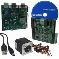
... AVR928: Sensorless methods to drive BLDC motors 1 Introduction This application note describes how to implement a sensorless commutation of BLDC motors with the ATAVRMC320 development kit. The ATmega32M1 is equipped with integrated peripherals that reduce the number of external components required in a BLDC application. The ATmega32M1 is suitable for sensorless commutation and for commutation with Hall sensors as well, but this application note focuses on the sensorless commutation ...
Page 2
... MC310 jumpers setting AVR172 2 The hardware includes the ATAVRMC310 and ATAVRMC300 boards which are the two parts of the ATAVRMC320 Starter kit. Please refer to the ATAVRMC300 and ATAVRMC310 user guides : - AVR430: MC300 Hardware User Guide - AVR470: MC310 Hardware User Guide The AVR172 firmware has been developed with the following jumper settings: Table 2-1 ...
Page 3
MC300 jumper settings 2.3 Power-supply 2.4 Motor 8306B-AVR-05/10 Figure 1. MC310 Jumpers configuration Table 2-1. ATAVRMC300 jumpers setting for sensorless control Designator Setting Function J2 none provide +5V to supply the ATAVRMC310 board On ATAVRMC300, Vm and Vin connectors ...
Page 4
ATmega32M1 Configuration 2.6 Technical Advices 2.6.1 Disconnecting the BLDC Motor 2.6.2 Ground and Power Wirings 3 Firmware 3.1 Main Flow chart AVR172 4 Line to Line Resistance : 1.8 ohm = R Back EMF : 3.66 V/Krpm = k_e ...
Page 5
Figure 2. Main flow chart The tasks are scheduled thanks to the g_tick produced each 1.024ms with Timer0. AVR172 5 ...
Page 6
MS_ALIGN phase The ALIGN phase forces the motor at a specific position. The time of this phase is controlled with ALIGN_TIME constant which is the ru_period_counter initial value (200 for MC310 motor). 3.3 RAMP_UP phase The ramp-up charateristics (duty-cycles ...
Page 7
Time of steps 3.3.2 Number of steps 3.3.3 Parameters tables 3.3.4 Sp1/pwm1 3.3.5 Sp2/pwm2 8306B-AVR-05/10 The step time is RAMP_UP_PERIOD = 50ms. The parameter : RAMP_UP_INDEX_MAX = 9, defines 10 steps ramp up. In firmware example, the tables have ...
Page 8
This confirms also the usual ratio = 10 between Sp1 and Sp2 which is defined in AVR498 Application Note. 3.4 LAST_RAMP_UP phase To avoid a shorten last step, this phase monitors the last ramp-up step to guarantee it is ended ...
Page 9
Running flowchart • 8306B-AVR-05/10 The flowchart is following : Figure 5. Closed-loop flowchart Motor_state is kept equal to MS_RUNNING mci_set_ref_speed() function updates the speed setpoint according to the potentiometer adjustment or the speed command received on serial transmission. In ...
Page 10
Sensorless Detection and Commutation Management AVR172 10 mc_control_speed(2*mci_get_ref_speed()) duty-cycle_reference is calculated from ref_speed and from monitored mci_get_measured_speed() measured_speed = (KSPEED * 4) / mci_measured_period with mci_measured_period calculated in the Interrupt vector of Analog Comparator 1. This interrupt uses Timer ...
Page 11
... User can communicate with firmware through RS232 with usual PC serial communication applications (i.e. Hyperterminal) or the Atmel “Motor Control Center” application which can be downloaded from Atmel web at url : At power up the following welcome message is received on terminal : “ATMEL Motor Control Interface”. ...
Page 12
USB communication AVR172 12 Figure 6. Motor Control Center Interface Communication can be achieved from PC to USB connector of MC310 board. The AVR470, MC310 Hardware User Guide details the configuration to be achieved. Communication port becomes a Virtual ...
Page 13
... BEEN ADVISED OF THE POSSIBILITY OF SUCH DAMAGES. Atmel makes no representations or warranties with respect to the accuracy or completeness of the contents of this document and reserves the right to make changes to specifications and product descriptions at any time without notice. Atmel does not make any commitment to update the information contained herein. Unless specifically provided otherwise, Atmel products are not suitable for, and shall not be used in, automotive applications. Atmel’ ...