DV330021 Microchip Technology, DV330021 Datasheet - Page 19
DV330021
Manufacturer Part Number
DV330021
Description
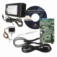
BOARD DEV DSPICDEM MCSM KIT
Manufacturer
Microchip Technology
Series
dsPIC™r
Datasheet
1.DM330022.pdf
(38 pages)
Specifications of DV330021
Main Purpose
Power Management, Motor Control
Embedded
*
Utilized Ic / Part
dsPIC33F
Primary Attributes
*
Secondary Attributes
*
Processor To Be Evaluated
dsPICDEM
Processor Series
dsPIC DSC
Interface Type
USB
Operating Supply Voltage
24 V
Silicon Manufacturer
Microchip
Silicon Core Number
DsPIC33F
Core Architecture
PIC
Core Sub-architecture
PIC33
Silicon Family Name
Piccolo
Lead Free Status / RoHS Status
Lead free / RoHS Compliant
Lead Free Status / RoHS Status
Lead free / RoHS Compliant, Lead free / RoHS Compliant
Available stocks
Company
Part Number
Manufacturer
Quantity
Price
Company:

Part Number:
DV330021
Manufacturer:
MICROCHIP
Quantity:
12 000


© 2009 Microchip Technology Inc.
3.1.2
Two shunt resistors are available for current sensing, one for each of the two motor
windings. In order to read both positive and negative currents, the amplifier circuit is
designed with an offset of V
current range of ±2.2A.
To calculate the amplifier gain, use the formula provided in Equation 3-1:
EQUATION 3-1:
The formula shown in Equation 3-1 is a simplified version of the complete formula and
is only valid when R
are needed, use the above formula to calculate R
and then replace both R
changes for R
The DC voltage supplied to the power stage is measured with a simple resistor divider.
To calculate the DC_REF signal used for this purpose use the formula provided in
Equation 3-2:
EQUATION 3-2:
This measurement is needed in the PI loop calculation and for algorithms such as
automatic motor induction and resistance identification.
3.1.3
The dsPICDEM MCSM Development Board features an overcurrent fault detection,
which triggers a PWM shutdown. Each phase current is amplified and then compared
with a fixed “safe” current value. A value of 1.7A is set for the dsPICDEM MCSM
Development Board; however, the user can change this limit by changing the resistor
divider made by R48 and R51. When either of the two phase currents is above the
“safe” current level, a Fault signal is triggered and the dsPIC DSC hardware module
automatically switches off all PWM outputs.
The Fault LED (D15) is active only when an overcurrent is present in the motor
windings. It will go inactive immediately after the internal dsPIC Fault circuit shuts down
the PWM pins. In this case, the LED will not be visible as the on-time is very short. The
Fault LED will only be visible if the Fault is persistent, that is when the software fault
shutdown is disabled.
For details about the PWM module Fault feature, please refer to Section 14. “Motor
Control PWM” (DS70187) in the “dsPIC33F Family Reference Manual”.
If the Fault LED is permanently active, power off the board immediately to avoid
damage to the power Mosfets.
Note:
Current Sensing
Fault Protection
The default gain value is 0.75 V/A, allowing a resolution of 67 µA/bit with
a 10-bit ADC.
39
and R
28
DC_REF SIGNAL CALCULATION FORMULA
AMPLIFIER GAIN CALCULATION FORMULA
= R
45
27
.
29
and R
REF
= R
Gain
33
= AV
DC_REF
35
= R
with the calculated resistor value. Make the same
=
WARNING
DD
34
R
/2. The amplifier gain allows for a maximum
SHUNT
and R
=
----- - DC_BUS
28
1
⋅
27
---------------------- -
R
28
= R
27
R
+
27
corresponding to the desired gain,
R
35
29
. If changes to the amplifier gain
DS70610A-page 19
Related parts for DV330021
Image
Part Number
Description
Manufacturer
Datasheet
Request
R

Part Number:
Description:
Manufacturer:
Microchip Technology Inc.
Datasheet:
Part Number:
Description:
Manufacturer:
Microchip Technology Inc.
Datasheet:
Part Number:
Description:
Manufacturer:
Microchip Technology Inc.
Datasheet:
Part Number:
Description:
Manufacturer:
Microchip Technology Inc.
Datasheet:
Part Number:
Description:
Manufacturer:
Microchip Technology Inc.
Datasheet:
Part Number:
Description:
Manufacturer:
Microchip Technology Inc.
Datasheet:
Part Number:
Description:
Manufacturer:
Microchip Technology Inc.
Datasheet:
Part Number:
Description:
Manufacturer:
Microchip Technology Inc.
Datasheet: