DV330021 Microchip Technology, DV330021 Datasheet
DV330021
Specifications of DV330021
Available stocks


Related parts for DV330021

DV330021 Summary of contents
Page 1
... Microchip Technology Inc. dsPICDEM™ MCSM Development Board User’s Guide DS70610A ...
Page 2
... REAL ICE, rfLAB, Select Mode, Total Endurance, TSHARC, UniWinDriver, WiperLock and ZENA are trademarks of Microchip Technology Incorporated in the U.S.A. and other countries. SQTP is a service mark of Microchip Technology Incorporated in the U.S.A. All other trademarks mentioned herein are property of their respective companies. ...
Page 3
... Hardware Architecture .................................................................................. 17 3.2 PIM Configuration ......................................................................................... 20 3.3 Board Connectors ........................................................................................ 24 3.4 User Interface Hardware .............................................................................. 27 Chapter 4. Troubleshooting 4.1 Common Problems ....................................................................................... 29 Appendix A. Board Layout and Schematics Appendix B. Electrical Specifications © 2009 Microchip Technology Inc. dsPICDEM™ MCSM DEVELOPMENT BOARD USER’S GUIDE Table of Contents DS70610A-page 3 ...
Page 4
... NOTES: DS70610A-page 4 © 2009 Microchip Technology Inc. ...
Page 5
... Chapter 3. “Hardware” – This chapter describes the hardware on the dsPICDEM MCSM Development Board. • Chapter 4. “Troubleshooting” – This chapter provides information for troubleshooting problems encountered while using the dsPICDEM MCSM Development Board. © 2009 Microchip Technology Inc. dsPICDEM™ MCSM DEVELOPMENT BOARD USER’S GUIDE Preface NOTICE TO CUSTOMERS ® ...
Page 6
... Appendix A. “Board Layout and Schematics” – This appendix provides diagrams of the hardware layout, as well as schematic diagrams for the dsPICDEM MCSM Development Board. • Appendix B. “Electrical Specifications” – This appendix provides pertinent electrical specifications for the dsPICDEM MCSM Development Board. DS70610A-page 6 © 2009 Microchip Technology Inc. ...
Page 7
... N‘Rnnnn Text in angle brackets < > Courier New font: Plain Courier New Italic Courier New Square brackets [ ] Curly braces and pipe character Ellipses... © 2009 Microchip Technology Inc. Represents Referenced books MPLAB Emphasized text ...is the only compiler... A window the Output window A dialog ...
Page 8
... Digital Signal Controller (DSC) devices. The dsPIC33F devices contain extensive Digital Signal Processor (DSP) functionality with a high performance 16-bit microcontroller (MCU) architecture. dsPIC33FJ32MC202/204 and dsPIC33FJ16MC304 Data Sheet (DS70283) This data sheet provides device specific information for the dsPIC33FJ32MC202/204 and dsPIC33FJ16MC304 motor control family of devices. DS70610A-page 8 © 2009 Microchip Technology Inc. ...
Page 9
... Programmers – The latest information on Microchip programmers. These include the MPLAB PM3 and PRO MATE Plus and PICkit™ 1development programmers. © 2009 Microchip Technology Inc. ® C18 and MPLAB C30 C compilers; MPASM™ ® ...
Page 10
... Local sales offices are also available to help customers. A listing of sales offices and locations is included in the back of this document. Technical support is available through the web site at: http://support.microchip.com DOCUMENT REVISION HISTORY Revision A (September 2009) This is the initial released revision of this document. DS70610A-page 10 © 2009 Microchip Technology Inc. ...
Page 11
... Communicate with a host computer or an external device via USB The dsPICDEM MCSM Development Board supports terminal voltages up to 80V and currents up to 3A. Refer to Appendix B. “Electrical Specifications” for more information. © 2009 Microchip Technology Inc. dsPICDEM™ MCSM DEVELOPMENT BOARD USER’S GUIDE ...
Page 12
... MCSM Development Board User’s Guide FIGURE 1-1: dsPICDEM MCSM DEVELOPMENT BOARD DS70610A-page 12 © 2009 Microchip Technology Inc. ...
Page 13
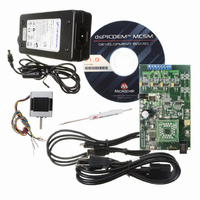
... RJ11 connector for programming a dsPIC DSC device (J1) - ICSP connector for programming the PIC18LF2450 USB-to-UART Bridge (J3) 1.3 WHAT’S INCLUDED Note: The MCSM Development Board is available in two configurations: • dsPICDEM MCSM Development Board • dsPICDEM MCSM Development Board Kit © 2009 Microchip Technology Inc. DS70610A-page 13 ...
Page 14
... MCSM Development Board CD ROM, which includes: - This user’s guide - Data sheets for dsPIC families - Example programs for use with the dsPIC DSC devices The dsPICDEM MCSM Development Board Kit with part number DV330021 contains the following: • dsPICDEM MCSM Development Board • dsPIC33FJ32MC204 Plug-In-Module (PIM) • ...
Page 15
... MOTOR CONFIGURATION TABLE J8 Pin Number Bipolar J8 Pin Name Series DC DC © 2009 Microchip Technology Inc. dsPICDEM™ MCSM DEVELOPMENT BOARD WARNING Bipolar Parallel Bipolar Half-winding Green+Yellow — Black Black+Yellow — — Orange Green+Orange Red Red+White — — Brown Blue+Brown Blue+White — ...
Page 16
... Build the project and download the program into the processor. 9. Click the Run icon when in Debug mode. Note: For more information on running stepper motors, refer to Section 1.4 “Reference Documents and Webinars”. DS70610A-page 16 th microstep step setting stops ® ICD 3 or MPLAB © 2009 Microchip Technology Inc. ...
Page 17
... PWM1L3 S1 PWM2H1 PWM2L1 DC_BUS dsPIC33FJXXXMCXXX PIM IMOTOR1 IMOTOR2 J1/J2 ICD2 FAULT J4 UART USB to USB Comparator © 2009 Microchip Technology Inc. DEVELOPMENT BOARD Chapter 3. Hardware J5 BP1 J7 Regulator BP2 15V Drivers M1 M2 Amplifier Amplifier Safe Current Level dsPICDEM™ MCSM USER’S GUIDE ...
Page 18
... Refer to Appendix A. “Board Layout and Schematics” for the complete schematic and PWM pin assignments. FIGURE 3-2: MOSFET PWM ASSIGNMENT T1 T2 PWM1H1 PWM1L1 PWM1H2 PWM1L2 DS70610A-page © 2009 Microchip Technology Inc. ...
Page 19
... For details about the PWM module Fault feature, please refer to Section 14. “Motor Control PWM” (DS70187) in the “dsPIC33F Family Reference Manual”. If the Fault LED is permanently active, power off the board immediately to avoid damage to the power Mosfets. © 2009 Microchip Technology Inc /2. The amplifier gain allows for a maximum REF ...
Page 20
... PIM (MA330014) • dsPIC33FJ32MC204 PIM (MA330017) • dsPIC33FJ128MC804 PIM (MA330018) Table 3-1, Table 3-2 and Table 3-3 describe the PIM configuration details. The dsPIC33FJ32MC204 and dsPIC33FJ128MC804 PIMs are pin-compatible and share the same table. DS70610A-page 20 © 2009 Microchip Technology Inc. ...
Page 21
... When using a dsPIC33FJ256MC710 it is necessary to set PIM pin 19 as FAULT_1. PIM Pin 19 can be configured for FAULT_1 or PWM2L1 signals by soldering the appropriate resistor as follows: • For FAULT_1 : Remove R87 and Solder R86 • For PWM2L1 : Remove R86 and Solder R87 (Default) © 2009 Microchip Technology Inc. (1) dsPIC33FJ256MC710 Pin Number ...
Page 22
... Solder R6, remove R5, R33 Solder R10, remove R9 — — — Solder R30, remove R22 Solder R29, remove R23 Solder R19 Solder R18 Solder R17 Solder R16 Solder R15 © 2009 Microchip Technology Inc. ...
Page 23
... PIM Pin 19 can be configured for FAULT_1 or PWM2L1 signals by soldering the appropriate resistor as follows: • For FAULT_1 : Remove R87 and Solder R86 • For PWM2L1 : Remove R86 and Solder R87 (Default) © 2009 Microchip Technology Inc. dsPIC33FJ32MC204 dsPIC33FJ128MC804 Pin Name PGED2/EMUD2/PWM1H3/RP10/CN16/RB10 — ...
Page 24
... ICSP™ programmer interface connector for programming the PIC18LF2450 USB-to-UART bridge USB interface port 24V power supply select jumper 24V Input power supply connector Auxiliary power supply select jumper Motor power connector J8 D3-D10 ® DSC device © 2009 Microchip Technology Inc. ...
Page 25
... Motor Connector (J8) The motor connector has eight terminals. Table 3-5 lists the functionality of each terminal. TABLE 3-5: Terminal Number © 2009 Microchip Technology Inc. MOTOR CONNECTOR DETAILS Designator Description Not connected Motor wire 1 (phase 1) DC bus voltage ...
Page 26
... PWM output for wire 2 bottom switch PWM output for wire 2 top switch PWM output for wire 3 top switch PWM output for wire 3 bottom switch PWM output for wire 4 bottom switch PWM output for wire 4 top switch Description © 2009 Microchip Technology Inc. ...
Page 27
... LEDs, which indicate the PWM pin status. When an LED is ON, the respective PWM pin is high. D14 Power-on status LED, which indicates the status of the D15 Fault LED; indicates an overcurrent. © 2009 Microchip Technology Inc. INDICATORS AND HUMAN INTERFACES Hardware Element Description + 3.3V regulator. DS70610A-page 27 ...
Page 28
... MCSM Development Board User’s Guide NOTES: DS70610A-page 28 © 2009 Microchip Technology Inc. ...
Page 29
... Switching noise is present and can be seen with an oscilloscope. Solution: To properly measure a signal, connect a probe to the desired signal and one to ground and perform a division. The signal that results is what the dsPIC DSC sees. © 2009 Microchip Technology Inc. dsPICDEM™ MCSM DEVELOPMENT BOARD DMCI CONNECTION FAILURE USER’ ...
Page 30
... MCSM Development Board User’s Guide NOTES: DS70610A-page 30 © 2009 Microchip Technology Inc. ...
Page 31
... Appendix A. Board Layout and Schematics FIGURE A-1: dsPICDEM™ MCSM DEVELOPMENT BOARD LAYOUT (TOP) © 2009 Microchip Technology Inc. dsPICDEM™ MCSM DEVELOPMENT BOARD USER’S GUIDE DS70610A-page 31 ...
Page 32
... MCSM Development Board User’s Guide FIGURE A-2: dsPICDEM™ MCSM DEVELOPMENT BOARD SCHEMATIC (SHEET DS70610A-page 32 © 2009 Microchip Technology Inc. ...
Page 33
... FIGURE A-3: dsPICDEM™ MCSM DEVELOPMENT BOARD SCHEMATIC (SHEET © 2009 Microchip Technology Inc. DS70610A-page 33 ...
Page 34
... MCSM Development Board User’s Guide FIGURE A-4: dsPICDEM™ MCSM DEVELOPMENT BOARD SCHEMATIC (SHEET DS70610A-page 34 © 2009 Microchip Technology Inc. ...
Page 35
... Power Rating Note 1: While driving two phases each through 4.6Ω winding resistance. 2: Maximum power tested is 40W. 3: Maximum theoretical power with no additional heat sink is: 80V * 1.7A = 135W. © 2009 Microchip Technology Inc. dsPICDEM™ MCSM DEVELOPMENT BOARD Condition Min — open, J7 closed ...
Page 36
... MCSM Development Board User’s Guide NOTES: DS70610A-page 36 © 2009 Microchip Technology Inc. ...
Page 37
... P PIM Configuration .................................................... 20 dsPIC33FJ128MC804 ...................................... 23 dsPIC33FJ12MC202 ........................................ 22 dsPIC33FJ256MC710 ...................................... 21 dsPIC33FJ32MC204 ........................................ 23 Plug-In Module (PIM) ............................................... 11 Power Stage ............................................................ 18 MOSFET Driver ................................................ 18 Switching Topology........................................... 18 © 2009 Microchip Technology Inc. dsPICDEM™ MCSM DEVELOPMENT BOARD USER’S GUIDE Index R Reading, Recommended ........................................... 8 S Schematics Sheet 1 of 3....................................................... 32 Sheet 2 of 3....................................................... 33 Sheet 3 of 3....................................................... 34 Signal Test Points ...
Page 38
... Philippines - Manila Tel: 63-2-634-9065 Fax: 63-2-634-9069 Singapore Tel: 65-6334-8870 Fax: 65-6334-8850 Taiwan - Hsin Chu Tel: 886-3-6578-300 Fax: 886-3-6578-370 Taiwan - Kaohsiung Tel: 886-7-536-4818 Fax: 886-7-536-4803 Taiwan - Taipei Tel: 886-2-2500-6610 Fax: 886-2-2508-0102 Thailand - Bangkok Tel: 66-2-694-1351 Fax: 66-2-694-1350 © 2009 Microchip Technology Inc. 03/26/09 ...