AT89STK-06 Atmel, AT89STK-06 Datasheet - Page 6
AT89STK-06
Manufacturer Part Number
AT89STK-06
Description
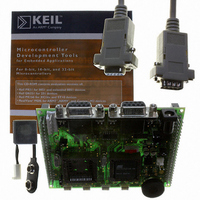
KIT DEMOBOARD 8051 MCU W/CAN
Manufacturer
Atmel
Datasheet
1.AT89STK-06.pdf
(22 pages)
Specifications of AT89STK-06
Main Purpose
Interface, CAN
Embedded
*
Utilized Ic / Part
T89C51CC01/CC02, AT89C51CC03
Primary Attributes
*
Secondary Attributes
*
Lead Free Status / RoHS Status
Contains lead / RoHS non-compliant


4339C–CAN–07/05
Hardware Description
2.3
2.3.1
2.3.2
2-4
J5 - 9V Battery connector:
RESET
Power-on RESET
RESET Push Button
Note:
Figure 2-2 . Male JACK Outlet and Wires
Caution: Do not mount more than one power supply source on AT89STK-06 board.
Figure 2-3 . EXT PWR Female Connector / Cable for 9V Battery
Caution: Do not mount more than one power supply source on AT89STK-06 Starter Kit.
Although the AT89C51CC03 & AT89C51AC3 microcontrollers have on-chip RESET
circuitry (c.f. microcontroller datasheet), the AT89STK-06 board provides to the
microcontroller a RESET signal witch can come from 2 different sources:
The on-board RC network acts as power-on RESET.
By pressing the RESET push button on the AT89STK-06 board, a warm RESET of the
microcontroller is performed.
– No specific polarization mandatory
– Need of a female 2 points connector
– Input supply from 6 up to 10V DC (example: 9V battery)
– Polarization mandatory
There is a diode voltage level between the negative output of the power supply
and the “GND”. This could introduce some gap of voltage during measurement
and instrumentation.
+
-
+
-
AT89STK-06 Demo Board Software Demo Guide
+
-
Related parts for AT89STK-06
Image
Part Number
Description
Manufacturer
Datasheet
Request
R

Part Number:
Description:
KIT EVAL APPL MASS STORAGE
Manufacturer:
Atmel
Datasheet:

Part Number:
Description:
KIT STARTER FOR AT89C5131
Manufacturer:
Atmel
Datasheet:

Part Number:
Description:
KIT STARTER FOR AT83C24
Manufacturer:
Atmel
Datasheet:

Part Number:
Description:
EVAL BOARD FOR AT83C26
Manufacturer:
Atmel
Datasheet:

Part Number:
Description:
KIT STARTER FOR MCU AT8XC5122/23
Manufacturer:
Atmel
Datasheet:

Part Number:
Description:
KIT STARTER FOR AT89C51RX2
Manufacturer:
Atmel
Datasheet:


Part Number:
Description:
8-Bit Microcontroller with 4K Bytes Flash
Manufacturer:
ATMEL Corporation
Datasheet:

Part Number:
Description:
DEV KIT FOR AVR/AVR32
Manufacturer:
Atmel
Datasheet:
Part Number:
Description:
INTERVAL AND WIPE/WASH WIPER CONTROL IC WITH DELAY
Manufacturer:
ATMEL Corporation
Datasheet:
Part Number:
Description:
Low-Voltage Voice-Switched IC for Hands-Free Operation
Manufacturer:
ATMEL Corporation
Datasheet:
Part Number:
Description:
MONOLITHIC INTEGRATED FEATUREPHONE CIRCUIT
Manufacturer:
ATMEL Corporation
Datasheet:
Part Number:
Description:
AM-FM Receiver IC U4255BM-M
Manufacturer:
ATMEL Corporation
Datasheet:
Part Number:
Description:
Monolithic Integrated Feature Phone Circuit
Manufacturer:
ATMEL Corporation
Datasheet: