AT89STK-06 Atmel, AT89STK-06 Datasheet - Page 20
AT89STK-06
Manufacturer Part Number
AT89STK-06
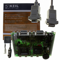
Description
KIT DEMOBOARD 8051 MCU W/CAN
Manufacturer
Atmel
Datasheet
1.AT89STK-06.pdf
(22 pages)
Specifications of AT89STK-06
Main Purpose
Interface, CAN
Embedded
*
Utilized Ic / Part
T89C51CC01/CC02, AT89C51CC03
Primary Attributes
*
Secondary Attributes
*
Lead Free Status / RoHS Status
Contains lead / RoHS non-compliant


Table 1. Default Configuration
AT89STK-06 Demo Board Software Demo Guide
Reference
SP1
SP2
SP3
JP1
JP2
JP3
JP4
JP5
JP6
Name
CC02 mode
X2_44
X2_52
EA
MUTE
CANRes
RTS
DTR
Batt
Function
For T89C51CC02/T89C5115 usage, allow to redirect the
ISP signal to P1.0, for hardware conditions.
Connect PLCC44 Xtal2 to XTAL2 of the generic extension
board
Connect PLCC52 Xtal2 to XTAL2 of the generic extension
board
ON : allows external execution
OFF: Internal code execution
ON : Enable C51 generic extension board buzzer
OFF: Disable C51 generic extension board buzzer
ON : Enable CAN terminator resistor
OFF: Disable CAN terminator resistor
ON : Enable RTS line to control ISP mode
OFF: Disable RTS line to control ISP mode
ON : Enable DTR line to drive MCU reset
OFF: Disable DTR line to drive MCU reset
ON : Enable Battery charge
OFF: Disable Battery charge
Appendix D: Default Configuration
Appendix D: Default Configuration
State
Open
Open
Open
Open (OFF)
Open (OFF)
Open (OFF)
Open (OFF)
Open (OFF)
Open (OFF)
4339C–CAN–07/05
4-19
Related parts for AT89STK-06
Image
Part Number
Description
Manufacturer
Datasheet
Request
R

Part Number:
Description:
KIT EVAL APPL MASS STORAGE
Manufacturer:
Atmel
Datasheet:

Part Number:
Description:
KIT STARTER FOR AT89C5131
Manufacturer:
Atmel
Datasheet:

Part Number:
Description:
KIT STARTER FOR AT83C24
Manufacturer:
Atmel
Datasheet:

Part Number:
Description:
EVAL BOARD FOR AT83C26
Manufacturer:
Atmel
Datasheet:

Part Number:
Description:
KIT STARTER FOR MCU AT8XC5122/23
Manufacturer:
Atmel
Datasheet:

Part Number:
Description:
KIT STARTER FOR AT89C51RX2
Manufacturer:
Atmel
Datasheet:


Part Number:
Description:
8-Bit Microcontroller with 4K Bytes Flash
Manufacturer:
ATMEL Corporation
Datasheet:

Part Number:
Description:
DEV KIT FOR AVR/AVR32
Manufacturer:
Atmel
Datasheet:
Part Number:
Description:
INTERVAL AND WIPE/WASH WIPER CONTROL IC WITH DELAY
Manufacturer:
ATMEL Corporation
Datasheet:
Part Number:
Description:
Low-Voltage Voice-Switched IC for Hands-Free Operation
Manufacturer:
ATMEL Corporation
Datasheet:
Part Number:
Description:
MONOLITHIC INTEGRATED FEATUREPHONE CIRCUIT
Manufacturer:
ATMEL Corporation
Datasheet:
Part Number:
Description:
AM-FM Receiver IC U4255BM-M
Manufacturer:
ATMEL Corporation
Datasheet:
Part Number:
Description:
Monolithic Integrated Feature Phone Circuit
Manufacturer:
ATMEL Corporation
Datasheet: