DM330021 Microchip Technology, DM330021 Datasheet - Page 22
DM330021
Manufacturer Part Number
DM330021
Description
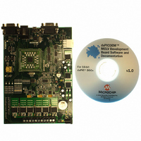
KIT DEMO DSPIC33 MCLV
Manufacturer
Microchip Technology
Series
dsPIC™r
Datasheet
1.DM330021.pdf
(40 pages)
Specifications of DM330021
Main Purpose
Power Management, Motor Control
Embedded
Yes, MCU, 16-Bit
Utilized Ic / Part
dsPIC33F
Primary Attributes
3-Ph BLDC or PMSM, 48V, 15A
Secondary Attributes
CAN, LIN, USB, RS-232 Interfaces
Processor To Be Evaluated
dsPIC33F
Interface Type
RS-232, USB
Lead Free Status / RoHS Status
Lead free / RoHS Compliant
Lead Free Status / RoHS Status
Lead free / RoHS Compliant, Lead free / RoHS Compliant
Available stocks
Company
Part Number
Manufacturer
Quantity
Price
Company:

Part Number:
DM330021
Manufacturer:
Microchip Technology
Quantity:
135
Company:
Part Number:
DM330021-2
Manufacturer:
MICROCHIP
Quantity:
12 000


dsPICDEM
DS70331A-page 18
2.2.4
The board has a MCP2021 High-Speed LIN Transceiver, which is connected to the
dsPIC33F device through jumpers JP4 and JP5. The LIN transceiver monitors the LIN
bus, conditions the incoming signal, and passes it to the UART module on the control
device. The LIN transceiver responds to a “Transmit Enable” from the control device by
conditioning an output signal and placing it on the LIN bus. A power-down mode turns
the transmitter and voltage regulator off, leaving only the receiver and wake-up circuits
in operation. The LIN circuit includes a Master/Slave jumper to accommodate a Master
node on the LIN bus. For more information, refer to the data sheet, MCP202X “LIN
Transceiver with Voltage Regulator” (DS22018).
2.2.5
The board uses an on-board PIC18 interface as a bridge between the UART and USB.
The PIC18 UART pins are connected to the dsPIC33F device through jumpers JP4 and
JP5.
2.2.6
The ICD 2 Connector is an RJ11 female connector (J11) that connects the MPLAB ICD
2 In-Circuit Debugger to the dsPIC33F device for programming and debugging
purposes. The ICD 2 can be connected to the board using 6-pin ICSP connector (J12).
2.2.7
The jumper J9 is a 6-pin connector that connects the PICkit™ 2 development
programmer to the PIC18F device. The board uses the on-board PIC18 interface as a
bridge between the UART and USB. The PIC18F can be programmed for USB
communication.
2.2.8
The connector J10 is an RS-232 interface port. The board uses the UART connector
to pass the UART signals from the dsPIC33F device to the dedicated UART IC
MAX3232CUE. The output of U14 is provided to the connector J10.
2.2.9
The motor connector (J7) has 11 terminals. Table 2-6 shows the functionality of each
terminal.
TABLE 2-6:
TM
MCLV Development Board User’s Guide
Pin
10
11
1
2
3
4
5
6
7
8
9
LIN Interface (J1)
USB Interface (J8)
ICD 2 Connector (J11- J12)
ICSP for PIC18 (J9)
RS-232 Connector (J10)
Motor Connector (J7)
MOTOR CONNECTOR DETAILS
Terminal Name
HALLA
HALLB
HALLC
GND
+5V
M1
M2
M3
G
+
-
External DC bus power supply
Ground
Motor winding phase 1
Motor winding phase 2
Motor winding phase 3
Ground
Hall sensors/Quadrature encoder power supply
Hall sensors ground
Hall A/QEA feedback
Hall B/QEB feedback
Hall C/INDEX feedback
Function
© 2008 Microchip Technology Inc.
Related parts for DM330021
Image
Part Number
Description
Manufacturer
Datasheet
Request
R

Part Number:
Description:
Manufacturer:
Microchip Technology Inc.
Datasheet:
Part Number:
Description:
Manufacturer:
Microchip Technology Inc.
Datasheet:
Part Number:
Description:
Manufacturer:
Microchip Technology Inc.
Datasheet:
Part Number:
Description:
Manufacturer:
Microchip Technology Inc.
Datasheet:
Part Number:
Description:
Manufacturer:
Microchip Technology Inc.
Datasheet:
Part Number:
Description:
Manufacturer:
Microchip Technology Inc.
Datasheet:
Part Number:
Description:
Manufacturer:
Microchip Technology Inc.
Datasheet:
Part Number:
Description:
Manufacturer:
Microchip Technology Inc.
Datasheet: