MCP3905EV Microchip Technology, MCP3905EV Datasheet - Page 14
MCP3905EV
Manufacturer Part Number
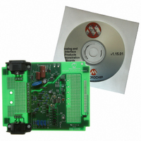
MCP3905EV
Description
BOARD DEMO FOR MCP3905
Manufacturer
Microchip Technology
Type
Other Power Managementr
Specifications of MCP3905EV
Main Purpose
Power Management, Energy/Power Meter
Embedded
No
Utilized Ic / Part
MCP3905/6
Primary Attributes
1-Phase, 120/220 VAC, On Board Transformerless AC/DC 5V Supply
Silicon Manufacturer
Microchip
Silicon Core Number
MCP3905A
Kit Application Type
Power Management
Application Sub Type
Energy Meter
Kit Contents
Board & Design Guides
Product
Power Management Modules
Lead Free Status / RoHS Status
Contains lead / RoHS non-compliant
Secondary Attributes
-
Lead Free Status / Rohs Status
Lead free / RoHS Compliant
For Use With/related Products
MCP3905
Lead Free Status / RoHS Status
Lead free / RoHS Compliant, Contains lead / RoHS non-compliant


MCP3905/6 Evaluation Board User’s Guide
DS51567A-page 10
2.3.4
Jumpers JP5 and JP6 select the output evaluation method. In this example, we are
selecting HF
FIGURE 2-5:
2.3.5
With the connections for J9 and J11 made in Figure 2-2, the 220V AC/DC power supply
circuit can be used as the +5V supply. Here we put JP4 in the “INT” position for internal
connection.
2.3.6
Once all jumper positions have been selected, connecting 220V with the correct L,G,N
connections and an appropriate load (10A in this example) will power both the
MCP3905/6 Evaluation Board and create the MCP3905 output (LED, BLINKING) in
Figure 2-5.
Step 4: Select desired output evaluation method
Step 5: Select +5V Source
Step 6: Connect Line and Load and Observe MCP3905 Output
OUT
connected to the LED for blink.
Connecting the MCP3905 High-Frequency Output to the LED.
HF
OUT
MCP3905
PULSE
JP6
© 2005 Microchip Technology Inc.
OPT
LED
Related parts for MCP3905EV
Image
Part Number
Description
Manufacturer
Datasheet
Request
R

Part Number:
Description:
Manufacturer:
Microchip Technology Inc.
Datasheet:
Part Number:
Description:
Manufacturer:
Microchip Technology Inc.
Datasheet:
Part Number:
Description:
Manufacturer:
Microchip Technology Inc.
Datasheet:
Part Number:
Description:
Manufacturer:
Microchip Technology Inc.
Datasheet:
Part Number:
Description:
Manufacturer:
Microchip Technology Inc.
Datasheet:
Part Number:
Description:
Manufacturer:
Microchip Technology Inc.
Datasheet:
Part Number:
Description:
Manufacturer:
Microchip Technology Inc.
Datasheet:
Part Number:
Description:
Manufacturer:
Microchip Technology Inc.
Datasheet: