MCP3905EV Microchip Technology, MCP3905EV Datasheet
MCP3905EV
Specifications of MCP3905EV


Related parts for MCP3905EV

MCP3905EV Summary of contents
Page 1
... Microchip Technology Inc. MCP3905A/06A Evaluation Board User’s Guide DS51567B ...
Page 2
... REAL ICE, rfLAB, Select Mode, Total Endurance, TSHARC, UniWinDriver, WiperLock and ZENA are trademarks of Microchip Technology Incorporated in the U.S.A. and other countries. SQTP is a service mark of Microchip Technology Incorporated in the U.S.A. All other trademarks mentioned herein are property of their respective companies. ...
Page 3
... A.2 Schematics and PCB Layout ....................................................................... 19 A.3 Board Schematic ........................................................................................ 20 A.4 Board Layout – Top Layer and Silk-screen ................................................. 21 A.5 Board Layout – Bottom Layer .................................................................... 22 Appendix B. Bill Of Materials (BOM) Worldwide Sales and Service .................................................................................... 26 © 2009 Microchip Technology Inc. Table of Contents USER’S GUIDE DS51567B-page 3 ...
Page 4
... MCP3905A/06A Evaluation Board User’s Guide DS51567B-page 4 © 2009 Microchip Technology Inc. ...
Page 5
... Appendix A. “Schematics and Layouts” – Shows the schematic and board layout diagrams for the MCP3905A/06A Evaluation Board. • Appendix B. “Bill Of Materials (BOM)” – Lists the parts used to build the MCP3905A/06A Evaluation Board. © 2009 Microchip Technology Inc. MCP3905A/06A EVALUATION BOARD USER’S GUIDE Preface NOTICE TO CUSTOMERS ® ...
Page 6
... Optional arguments mcc18 [options] file [options] Choice of mutually exclusive errorlevel {0|1} arguments selection Replaces repeated text var_name [, var_name...] Represents code supplied by void main (void) user { ... } © 2009 Microchip Technology Inc. Examples ® IDE User’s Guide ...
Page 7
... Customers should contact their distributor, representative or field application engineer (FAE) for support. Local sales offices are also available to help customers. A listing of sales offices and locations is included in the back of this document. Technical support is available through the web site at: http://support.microchip.com. © 2009 Microchip Technology Inc. Preface DS51567B-page 7 ...
Page 8
... MCP3905A/06A Evaluation Board User’s Guide DOCUMENT REVISION HISTORY Revision B (August 2009) • Update from MCP3905/06 to MCP3905A/06A devices. Revision A (August 2005) • Initial Release of this Document. DS51567B-page 8 © 2009 Microchip Technology Inc. ...
Page 9
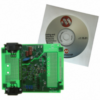
... Unit (MCU), are easily designed using this evaluation board as the prototype Analog Front-End (AFE). 1.3 WHAT THE MCP3905A/06A EVALUATION BOARD KIT INCLUDES This MCP3905A/06A Evaluation Board Kit includes: • The MCP3905A/06A Evaluation Board (with MCP3905A installed)(102-00057) • Important Information Sheet © 2009 Microchip Technology Inc. USER’S GUIDE ® Microcontroller DS51567B-page 9 ...
Page 10
... MCP3905A/06A Evaluation Board User’s Guide NOTES: DS51567B-page 10 © 2009 Microchip Technology Inc. ...
Page 11
... This connection can also be isolated using an on-board, optical-isolation IC. Output LEDs Screw Connector for Line and Shunt or CT FIGURE 2-1: © 2009 Microchip Technology Inc. ® microcontroller demonstration (demo) ® DSC development system meter PICtail™ Daughter Board Header PICtail™ ...
Page 12
... Figure 2-2. J11 FIGURE 2-2: system is biased to the line-side of the two-wire power supply. DS51567B-page 12 High Low CH0+ CH0- CH1A CH1B 250 µΩ Shunt Example Input Prototype Area Connections Using Shunt. The J12 © 2009 Microchip Technology Inc. ...
Page 13
... In Figure 2-4, the voltage divider and potentiometer are connected to the positive input, while the negative input is connected to A FIGURE 2-4: © 2009 Microchip Technology Inc. Installation and Operation and R should be left open when using a shunt. JP3, JP13 and ...
Page 14
... Appendix A. “Schematics and Layouts” and Appendix B. “Bill Of Materials (BOM)” for a list of the parts used to build the MCP3905A/06A Evaluation Board. DS51567B-page 14 connected to the LED for blink. MCP3905A HF PULSE OUT Connecting the MCP3905A High-Frequency Output to the LED. OPT LED JP6 © 2009 Microchip Technology Inc. ...
Page 15
... Jumpers and shunts for both logic-high and logic-low are included for all gain and frequency constant selections, with filter options Off and On columns being clearly labelled. FIGURE 2-7: © 2009 Microchip Technology Inc. Installation and Operation High Low CH0+ CH0- CH1A CH1B 250 µ ...
Page 16
... JP3 R 1 kΩ Ω Channel 0 Jumpers for 250 µ Shunt Selection. short JP3 Example of Channel 0 Jumpers with 60 23 CH0 0.033 µF 24 CH0 0.033 µ CH0 kΩ 20 0.033 µ CH0 kΩ 21 0.033 µF Ω Burden Resistor for © 2009 Microchip Technology Inc. ...
Page 17
... Calibration Experiments, Labeled Circuit B on the PCB Silk-Screen. 6 2.5.7 MCP3905A Center-of-board, 24-lead surface-mount package. Refer to the MCP3905A Data Sheet, “Energy Metering IC with Active Real Power Pulse Output” (DS21948) for a detailed description. © 2009 Microchip Technology Inc. Installation and Operation Option – Circuit A GND kΩ ...
Page 18
... MCU header, GND the DC RMS should change 16 ® MCUs. RA5 1 RA4 2 RA3 3 RC5 4 RC4 5 RC3 6 RA0 7 RA1 8 RA2 9 RC0 10 RC1 11 RC2 12 VCC 13 ® PIC _MCU_GND 14 Standard PICtail™ Daughter Board Connector Ω pull-up resistor to the PICtail™ © 2009 Microchip Technology Inc. ...
Page 19
... Board Schematic • Board – Top Layer and Silk-Screen • Board – Bottom Layer A.2 SCHEMATICS AND PCB LAYOUT The layer order is shown in Figure A-1. FIGURE A-1: © 2009 Microchip Technology Inc. Top Layer Bottom Layer Layer Order. USER’S GUIDE DS51567B-page 19 ...
Page 20
... MCP3905A/06A Evaluation Board User’s Guide A.3 BOARD SCHEMATIC + - 2 1 DS51567B-page © 2009 Microchip Technology Inc. ...
Page 21
... A.4 BOARD LAYOUT – TOP LAYER AND SILK-SCREEN © 2009 Microchip Technology Inc. Schematics and Layouts DS51567B-page 21 ...
Page 22
... MCP3905A/06A Evaluation Board User’s Guide A.5 BOARD LAYOUT – BOTTOM LAYER DS51567B-page 22 © 2009 Microchip Technology Inc. ...
Page 23
... JP5 HEADER,.1"ST MALE,2RW,8PIN, .025"PST,.23"GOLDTAIL (10) Note 1: The components listed in this Bill of Materials are representative of the PCB assembly. The released BOM used in manufacturing uses all RoHS-compliant components. © 2009 Microchip Technology Inc. Description Manufacturer EPCOS Panasonic Nichon Panasonic - ECG Panasonic - ECG ...
Page 24
... Yageo America Yageo America Part Number 2X2SG-R DT128V3P-R 2012JH-R SIOV-S20K275 104-00057 MFR-25FBF-1K00 RC1206JR-07820RL ERJ-6ENF4750V ERJ-6ENF4751V MFR-25FBF-30R1 ERJ-6ENF1002V ERJ-8ENF20R0V RSF100JB-470K ERJ-8ENF10R0V B3F-1000 5012 ® MCP3905A-I/SS KA78L05AD ® PS2501-1-A 3296Y-1-102LF 3296Y-1-104LF 3296Y-1-504LF ECS-35-17-4X EXC-ELSA39 MFR-25FBF-332K MFR-25FBF-499R SJ-5518 (BLACK) © 2009 Microchip Technology Inc. ...
Page 25
... NOTES: © 2009 Microchip Technology Inc. Bill Of Materials (BOM) DS51567B-page 25 ...
Page 26
... Fax: 886-3-6578-370 Taiwan - Kaohsiung Tel: 886-7-536-4818 Fax: 886-7-536-4803 Taiwan - Taipei Tel: 886-2-2500-6610 Fax: 886-2-2508-0102 Thailand - Bangkok Tel: 66-2-694-1351 Fax: 66-2-694-1350 © 2009 Microchip Technology Inc. EUROPE Austria - Wels Tel: 43-7242-2244-39 Fax: 43-7242-2244-393 Denmark - Copenhagen Tel: 45-4450-2828 Fax: 45-4485-2829 France - Paris Tel: 33-1-69-53-63-20 ...